TOE100G-IP on Alveo card Demo Instruction
Rev1.0 6-Jul-23
3 Test result when using Accelerator system and 100G Ethernet card
4 Test result when using two Accelerator systems
4.3 Send Data Test (Server to Client)
4.4 Receive Data Test (Client to Server)
1 Overview
This document shows the example to run TOE100G-IP on Alveo card demo by using two test environments. First is run by using Accelerator system transferring TCP payload data with Test PC by using 100Gb Ethernet card. The test application must be run on Test PC. Test performance on the first environment is limited by the resource on Test PC. Second is run by using two Accelerator systems transferring TCP payload data to each other. The second test environment can achieve the best performance for transferring TCP payload data via 100Gb Ethernet.
In the document, topic 2 shows the example to set up 100Gb Ethernet card on Test PC to get the good performance for transferring data via 100Gb Ethernet under the first test environment, Accelerator system and Test PC by 100G Ethernet card. Topic 3 shows the example console and test result when running under the first test environment. Topic 4 shows the example console when running the second test environment, two Accelerator systems. More details of each topic are described as follows.
2 Test PC Setup
Before running demo, please check the network setting on Test PC. The examples for setting 100Gb Ethernet card on two OSes (Windows10 OS and Ubuntu 20.04.1 OS) are shown.
2.1 Windows 10 OS
1) Checking the IP address of the 100G Ethernet card, as shown in Figure 2‑1.
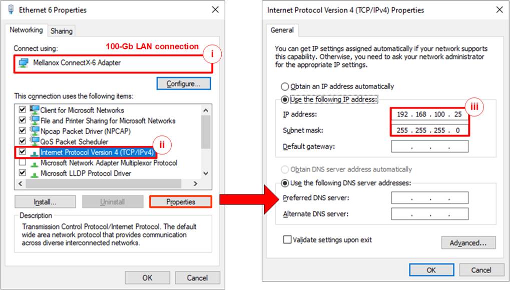
Figure 2‑1 Setting IP address on Windows OS
i. Open Local Area Connection Properties of 100-Gb connection, as shown in the left window of Figure 2‑1.
ii. Select “TCP/IPv4” and then click Properties.
iii. Set IP address = 192.168.100.25 and Subnet mask = 255.255.255.0, as shown in the right window of Figure 2‑1.
2) Enable jumbo frame to the Ethernet card, as shown in Figure 2‑2.
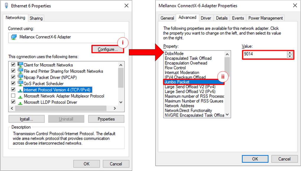
Figure 2‑2 Set frame size = Jumbo frame
i. On Local Area Connection Properties window, click “Configure” as shown in the left window of Figure 2‑2.
ii. On Advanced Tab, select “Jumbo Packet”. Set Value to “9014 Bytes” for Jumbo Frame support, as shown in the right window of Figure 2‑2.
Note: If setting “Disabled”, Jumbo frame is not supported and the performance may be reduced.
3) Disable the flow control and interrupt moderation of the Ethernet card, as shown in Figure 2‑3.

Figure 2‑3 Disable Flow Control and Interrupt Moderation
i. Select “Flow Control” and set value to “Disabled”, as shown in the left window of Figure 2‑3.
ii. Select “Interrupt Moderation” and set value to “Disabled”, as shown in the right window of Figure 2‑3.
iii. Click “OK” button to save and exit all setting windows.
4) Check the plan of Power options to get the better performance on Windows 10 OS.
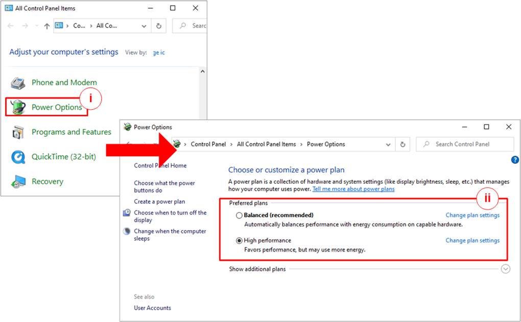
Figure 2‑4 Power options
i. Open Control Panel and select Power Options, as shown in the left window of Figure 2‑4.
ii. Change setting to High Performance, as shown in the right window of Figure 2‑4.
2.2 Ubuntu 20.04.1 OS
1) Open the terminal to start Ethernet interface configuration.
2) To list the logical name of 100G Ethernet port on Linux terminal, use following command.
>> sudo lshw -C network
Figure 2‑5 shows the results when running the command. “enp1s0f0” is the used 100Gb Ethernet interface.

Figure 2‑5 Display logical name of 100G Ethernet port
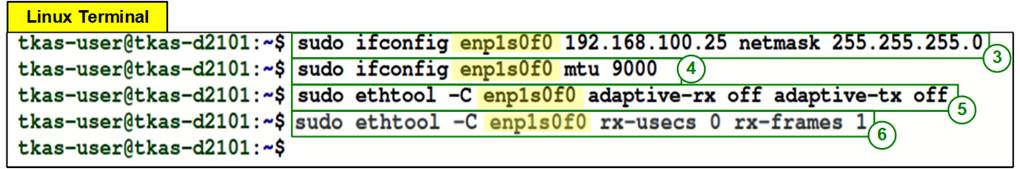
Figure 2‑6 IP address and Ethernet interface setting
3) Type “ifconfig <interface> <ipaddr_value> netmask <netmask_value>” to set target IP address and Subnet mask to the desired port of the Ethernet card.
a) Desired (interface) port of Ethernet card = “enp1s0f0”
b) Set IP address = 192.168.100.25, Subnet mask = 255.255.255.0
>> sudo ifconfig enp1s0f0 192.168.100.25 netmask 255.255.255.0
4) Type “ifconfig <interface > mtu <mtu_value>” to set maximum transfer unit over TCP/IP. It needs to set mtu_value = 9000 to support jumbo frame packet.
>> sudo ifconfig enp1s0f0 mtu 9000
5) Turn off Rx-Tx latency improvement algorithm by “sudo ethtool -C <interface> adaptive-rx off adaptive-tx off”.
>> sudo ethtool -C enp1s0f0 adaptive-rx off adaptive-tx off
6) Set the highest rate of Rx interrupt by “sudo ethtool -C <interface> rx-usecs 0 rx-frames 1”. This setting executes PC interrupt every time that PC receives a packet.
>> sudo ethtool -C enp1s0f0 rx-usecs 0 rx-frames 1
3 Test result when using Accelerator system and 100G Ethernet card
3.1 Display TCPIP parameters
Select ‘0’ to check current parameter in the demo. There are eight parameters in Client/Server mode or nine parameters in Fixed MAC mode displayed on the console.
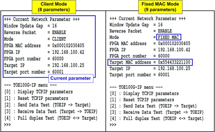
Figure 3‑1 Display current parameter result
1) Window Update Gap: Set threshold value to transmit window update packet. Valid value is 0x00 – 0x3F (0-63). The unit size of threshold value is 1 Kbyte. Default value is 16 (Window update packet every 16 Kbytes).
2) Reverse Packet: This flag is enabled to allow the IP sending the retransmitted packet when IP waits Windows update packet returned from the target for long time. Default value is ENABLE.
3) Mode: Set mode to TOE100G-IP to initialize in Server, Client, or Fixed MAC. To run with Test PC, please input ‘0’ to initialize the IP in client mode.
4) FPGA MAC address: 48-bit hex value to be MAC address of the Accelerator system. Default value is 0x000102030405.
5) FPGA IP: IP address of the Accelerator system. Default value is 192.168.100.42.
Note: This value is used to be Server IP address parameter of the application on Test PC.
6) FPGA port number: Port number of the Accelerator system. Default value is 60000.
Note: This value is used to be Server port of the application on Test PC.
7) Target MAC address (displayed when running Fixed MAC mode only): 48-bit hex value to be MAC address of the target device. Default value is 0x554433221100.
8) Target IP: IP address of the target device (100 Gb Ethernet on PC). Default value is 192.168.100.25.
9) Target port number: Port number of the target device to transfer TCP payload data. Default value is 60001.
To change some parameters, user can set by using menu [1].
3.2 Reset TCPIP parameters
Select ‘1’ to reset the IP and change IP parameters.
This menu is used to change IP parameters or send reset to TOE100G-IP. After user selects this menu, the current parameters are displayed on the console. User enters ‘x’ to use the same parameters while other keys are entered to change some parameters. After the parameters are fixed, TOE100G-IP is reset and start the initialization process.
There are eight or nine parameters to set in this menu. Each parameter is verified before loading to TOE100G-IP. If the input is not valid, the parameter does not change. After loading all parameters, the IP is reset. The description of each parameter is shown in topic 3.1 (Display TCPIP parameters) and the range of each parameter is described as follows.
1) Mode: Input ‘0’ to initialize the IP as client mode.
Note: When Test PC and Accelerator system are connected in different network which cannot communicate by ARP process, it needs to run TOE100G-IP in Fixed MAC mode to set MAC address manually via the console instead of using ARP process
2) Reverse Packet: Set ‘0’ to disable or ‘1’ to enable this feature.
3) Window Update Gap: Set threshold value to transmit window update packet. Valid value is 0x00 – 0x3F (0-63). The unit size of threshold value is 1 Kbyte. Default value is 16 (window update packet every 16 Kbytes).
4) FPGA MAC address: Input 12 digits of hex value. Add “0x” as a prefix to input as hex value.
5) FPGA IP address: A set of four decimal digits is separated by “.” (dot character). The valid range of each decimal digit is 0-255.
6) FPGA port number: Valid range is 0-65535.
7) Target MAC address (displayed when running Fixed MAC mode only): Input 12 digits of hex value. Add “0x” as a prefix to input as hex value.
8) Target IP address: A set of four decimal digits, similar to FPGA IP address. This value is IP address of Test PC.
9) Target port number: Valid range is 0-65535.
After finishing parameter assignment, the updated parameters are displayed on the console. Next, the reset signal is sent to the IP to initialize the IP by using new parameters. Finally, “IP initialization complete” is shown after IP completes initialization process, as shown in Figure 3‑2.
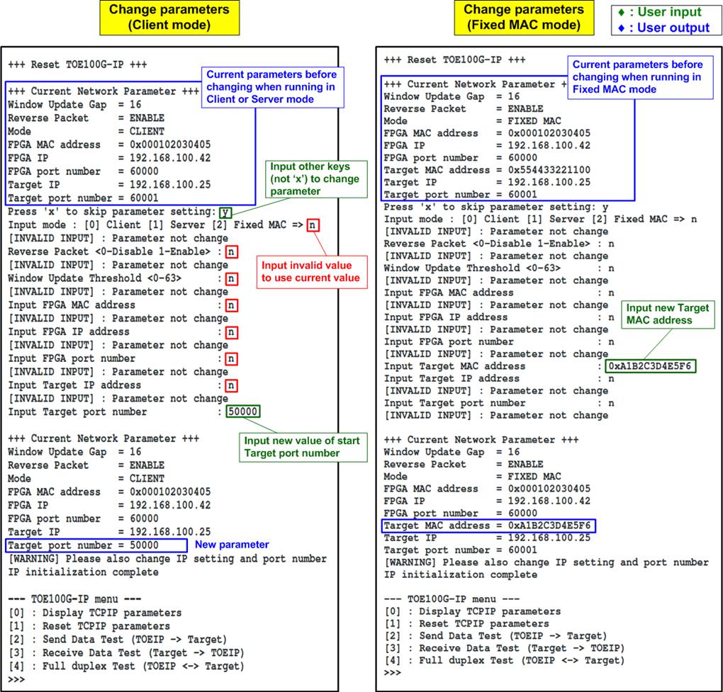
Figure 3‑2 Change IP parameter and reset
3.3 Send Data Test
To transfer data from Accelerator system to 100G Ethernet card on Test PC, select ‘2’ to run send data test on Accelerator system and run “tcpdatatest” on Test PC to receive data. User inputs test parameters for sending data on the console. On Test PC, user inputs test parameters of “tcpdatatest” to receive data via Command prompt (Windows OS) or Terminal (Ubuntu OS). The sequence to run the test is shown as follows.
1) On the Accelerator system console, input three parameters under send data test menu.
a) Input transfer size: Unit of transfer size is byte. Valid value is 0x40 - 0x3F_FFFF_FFC0. The input must be aligned to 64. The input is decimal unit when input only digit number. User adds “0x” to be a prefix for hexadecimal unit.
b) Input packet size: Unit of packet size is byte. Valid value is 64 – 8960. The input must be aligned to 64. The input is decimal unit when input only digit number. User adds “0x” to be a prefix for hexadecimal unit.
Note: If packet size is more than 1408, the packet output from TOE100G-IP is jumbo frame. In this case, Test PC must support jumbo frame.
c) Enable data generation: ‘1’ - Use 32-bit incremental value, ‘0’ – Use null value.
d) Input Mode: The connection mode of Accelerator system. Input ‘1’ to open connection by Server mode (Passive open).
2) If all inputs are valid, the recommended parameters to run test application on Test PC are displayed. Next, “Wait Open connection …” is displayed to wait until the application is run on Test PC.
3) On Command prompt/Terminal, input test parameters following the recommended value. There are six parameters for “tcpdatatest”.
For Windows OS,
>> tcpdatatest <mode> <dir> <server IP> <server port> <bytelen> <pattern>
For Ubuntu OS,
>> ./tcpdatatest <mode> <dir> <server IP> <server port> <bytelen> <pattern>
a) Mode: Input ‘c’ to run Test PC as a client.
b) Dir: Input ‘r’ to run Test PC for receiving and verifying test data from Accelerator system
c) Server IP: Input the same value as IP address of Accelerator system
d) Server port: Input the same value as port number of Accelerator system
e) Bytelen: Input the same value as “Input transfer size” of step 1a)
f) Pattern: Input ‘1’ to verify data from Accelerator system or ‘0’ to not verify data
4) After running the application on Test PC, the port is created. Current amount of transferred data is displayed on Accelerator console (transmitted data) and Command prompt/Terminal (received data) every second.
5) The Accelerator system closes the connection. Then, “Send data complete” message is displayed on the console. Finally, total transfer size and performance are displayed on the console (transmit performance) and Command prompt/Terminal (receive performance).
Figure 3‑3 shows the example of send data test when using non-jumbo frame size with enabling data verification on Command prompt/Terminal. The left window is Accelerator system console operating as Server and the right window is Command prompt/Terminal on Test PC operating as Client.
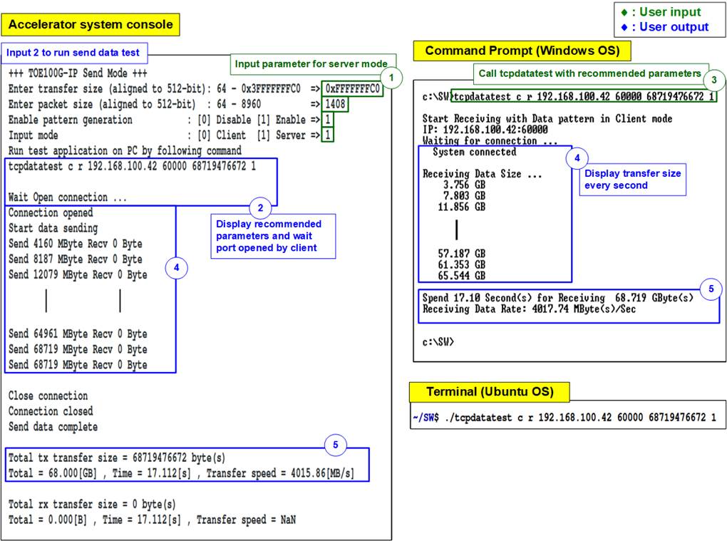
Figure 3‑3 Send data test by using non-jumbo frame with data verification
Figure 3‑4 shows the example performance when running by using maximum packet size. The result of this test and result from the test in Figure 3‑3 shows that running with non-jumbo frame size archives higher performance than maximum packet size. Under 100G Ethernet test environment, it is found that when using the maximum packet size, all data in the buffer of TOE100G-IP is completely transferred to Test PC very fast while ACK packet returned from Test PC which is applied to clear the buffer has much latency. Therefore, TOE100G-IP pauses data sending to wait until ACK packet is returned before sending the next data. The maximum performance is achieved when the packet size can balance the time usage for transmitting data and receiving the ACK packet. However, the performance may not stable because the OS assigns different priority to the application while running the test.
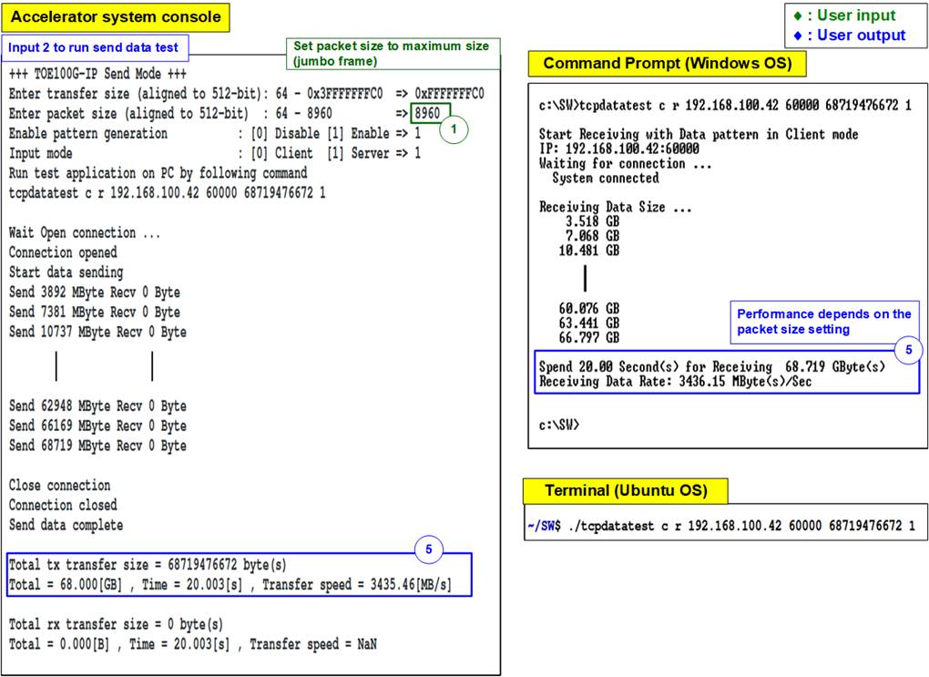
Figure 3‑4 Send data test by using jumbo frame with data verification
Figure 3‑5 shows the example performance when running by using non-jumbo frame size with disabling data verification. The result shows no significant difference between enabling or disabling the data verification, comparing to Figure 3‑3.
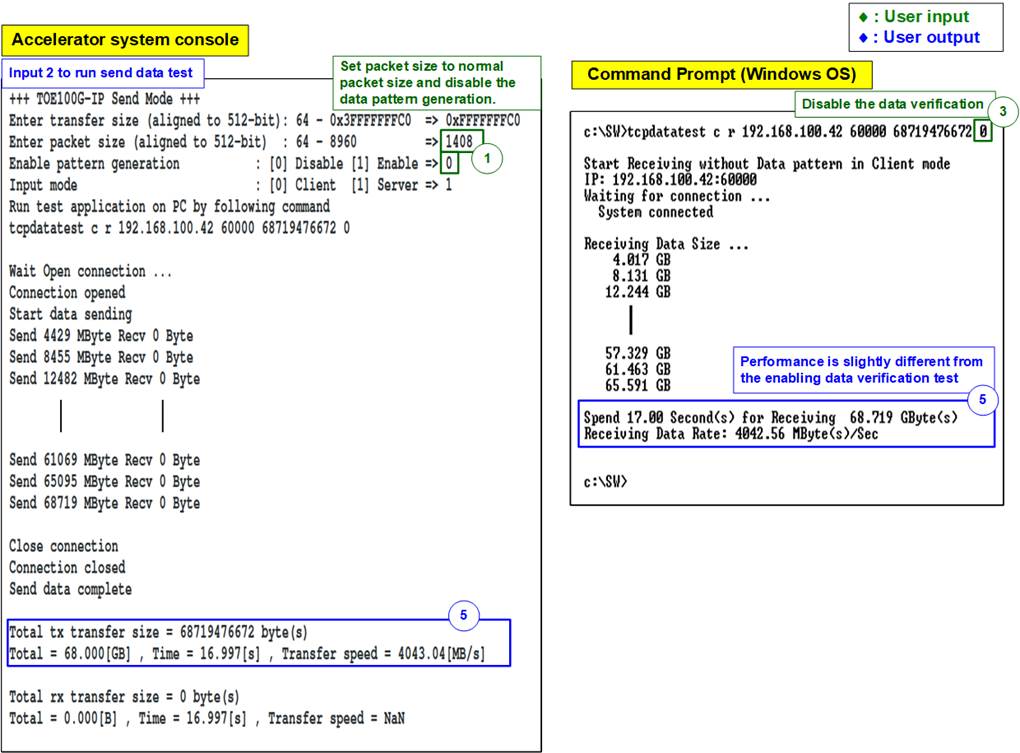
Figure 3‑5 Send data test using non-jumbo frame without data verification
If the input is invalid, “Out-of-range input” or “Invalid input” is displayed. After that, the operation is cancelled, as shown in Figure 3‑6 - Figure 3‑7.
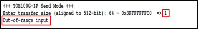
Figure 3‑6 Error from invalid input

Figure 3‑7 Error from out-of-range input
3.4 Receive Data Test
To transfer data from 100G Ethernet card on Test PC to Accelerator system, select ‘3’ to run receive data test on the Accelerator system and run “tcpdatatest” on Test PC to send data. User inputs test parameters for receiving data on the Accelerator system console. On Test PC, user inputs test parameters of “tcpdatatest” to send data on Command prompt (Windows OS) or Terminal (Ubuntu OS). The sequence to run the test is shown as below.
1) On the Accelerator system console, input three parameters in receive data test.
a) Input transfer size: Unit of transfer size is byte. Valid value is 0x40 - 0x3F_FFFF_FFC0. The input must be aligned to 64. The input is decimal unit when input only digit number. User adds “0x” to be a prefix for hexadecimal unit.
b) Input data verification mode: Set ‘0’ to disable data verification or ‘1’ to enable data verification sent from Test PC.
c) Input Mode: The connection mode of Accelerator system. Input ‘1’ to open connection by Server mode (Passive open).
2) If all inputs are valid, the recommended parameters to run test application on Test PC are displayed. Next, “Wait Open connection …” is displayed to wait until the application is run on Test PC.
3) On Command prompt/Terminal, input test parameters following the recommended value. There are six parameters for “tcpdatatest”.
For Windows OS,
>> tcpdatatest <mode> <dir> <server IP> <server port> <bytelen> <pattern>
For Ubuntu OS,
>> ./tcpdatatest <mode> <dir> <server IP> <server port> <bytelen> <pattern>
a) Mode: Input ‘c’ to run Test PC as a client.
b) Dir: Input ‘t’ to run Test PC for sending test data to Accelerator system
c) Server IP: Input the same value as IP address of Accelerator system
d) Server port: Input the same value as port number of Accelerator system
e) Bytelen: Input the same value as “Input transfer size” of step 1a)
f) Pattern: Input the same value as “Input data verification mode” of step 1b). Select ‘0’ to send dummy data or ‘1’ to send incremental data.
4) After running the test application, the port is created. Current amount of transferred data is displayed on Accelerator system console (received data) and Command prompt/Terminal (transmitted data) every second.
5) “Connection closed” and “Received data completed” are displayed on Accelerator system console after Test PC finishes sending all data and closing the connection. Finally, total transfer size and performance are displayed on Accelerator system console (receive performance) and Command prompt/Terminal (transmit performance).
Figure 3‑8 shows the example of receive data test when data verification mode on the Accelerator system is enabled and incremental data is sent by Test PC. The left window is test result on the Accelerator system console while the right window is test result on Command prompt/Terminal on Test PC.
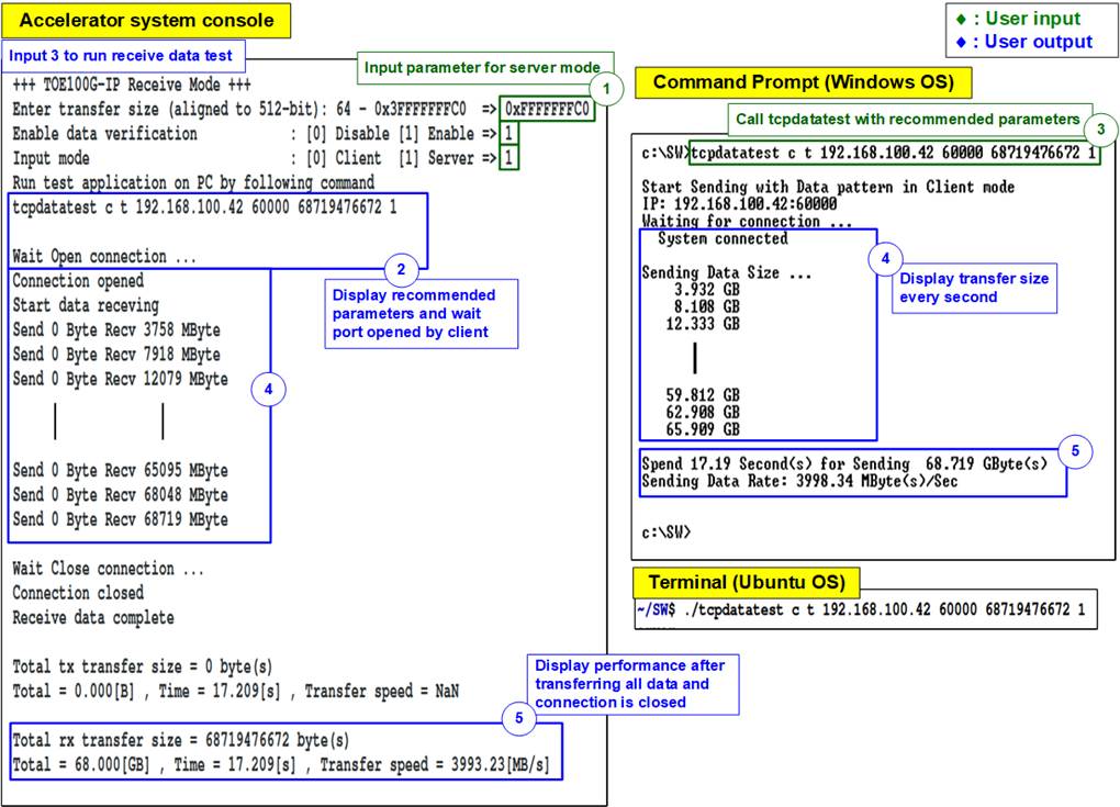
Figure 3‑8 Receive data test with data verification
Figure 3‑9 shows the example of receive data test when data verification mode on the Accelerator system is disabled and dummy data is sent by Test PC. Comparing to Figure 3‑8, the performance in the test environment is increased when running by sending the dummy data instead of incremental data.
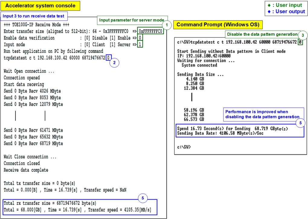
Figure 3‑9 Receive data test without data verification
Figure 3‑10 shows the example of error when data verification is failed. In the example, the error is caused from mismatch verification mode value. The Accelerator system enables data verification while “tcpdatatest” sends dummy data. The error message is displayed on Accelerator system console.

Figure 3‑10 Receive data test when data verification is failed
3.5 Full duplex Test
Select ‘4’ to run full duplex test on Accelerator system and Test PC to transfer data in both directions at the same time. User inputs test parameters on the Accelerator system console. and on Test PC Command prompt (Windows OS) or Terminal (Ubuntu OS). The application that is called on Test PC is “tcp_client_txrx_40G” (Windows OS) or “tcp_client_txrx” (Ubuntu OS) which is applied to send and receive data by using the same port number. The sequence to run the test is shown as below.
1) On the Accelerator system console, input four parameters in full duplex test.
a) Input transfer size: Unit of transfer size is byte. Valid value is 0x40 - 0x3F_FFFF_FFC0. The input must be aligned to 64. The input is decimal unit when input only digit number. User adds “0x” to be a prefix for hexadecimal unit. This value must be equal to total transfer size, set on test application.
b) Input packet size: Unit of packet size is byte. Valid value is 64 – 8960. The input must be aligned to 64. The input is decimal unit when input only digit number. User adds “0x” to be a prefix for hexadecimal unit.
c) Input data verification/generation mode:
· Set ‘0’ to disable data verification and pattern data generation.
· Set ‘1’ to enable data verification and pattern data generation.
The data generation is used to send to Test PC and the data verification is used to verify the data from Test PC.
d) Input Mode: The connection mode of Accelerator system. Input ‘1’ to open connection by Server mode (Passive open).
2) If all inputs are valid, the recommended parameters to run test application on Test PC are displayed. Next, “Wait Open connection …” is displayed to wait until the application on Test PC is run.
3) On Test PC Command prompt/Terminal, input test parameters following the recommended value. There are four parameters for “tcp_client_txrx_40G”/”tcp_client_txrx”.
For Windows OS,
>> tcp_client_txrx_40G <server IP> <server port> <bytelen> <pattern>
For Ubuntu OS,
>> tcp_client_txrx <server IP> <server port> <bytelen> <pattern>
a) Server IP: Input the same value as IP address of Accelerator system
b) Server port: Input the same value as port number of Accelerator system
c) ByteLen: Total transfer size in byte unit. Input the same value as “Input transfer size” of step 1a).
d) Pattern: Input the same value as “Input data verification/generation mode” of step 1c). Select ‘0’ to send dummy data or ‘1’ to send incremental data.
4) After running the test application, the port is created. While transferring data, current transfer size is displayed on the Accelerator system console and Test PC Command prompt/Terminal every second.
5) Test PC (run as Client) closes the connection after transferring the data in both directions. Finally, total transfer size and performance are displayed on the Accelerator system console and Test PC Command prompt/Terminal.
There are two-second time gap after step 5) for user to stop the operation by pressing any keys on both consoles. Otherwise, repeat step 4) – 5) as forever loop.
Figure 3‑11 shows the example when running full duplex with data verification. The left window is the test result on the Accelerator system console while the right window is the test result on Test PC Command prompt/Terminal.
Note: The performance when running the full duplex test is much reduced if it compares to the half-duplex tests (Send/Receive) because there are more tasks for OS of the Test PC to handle. Also, there is an issue when running tcp_client_txrx_40G application without data verification on some Windows10 versions. The performance can be much reduced.
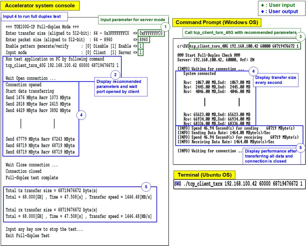
Figure 3‑11 Full duplex test with data verification
4 Test result when using two Accelerator systems
4.1 Display TCPIP parameters
Select ‘0’ to check current parameter in the demo. There are eight parameters in Client/Server mode or nine parameters in Fixed MAC mode displayed on the console.
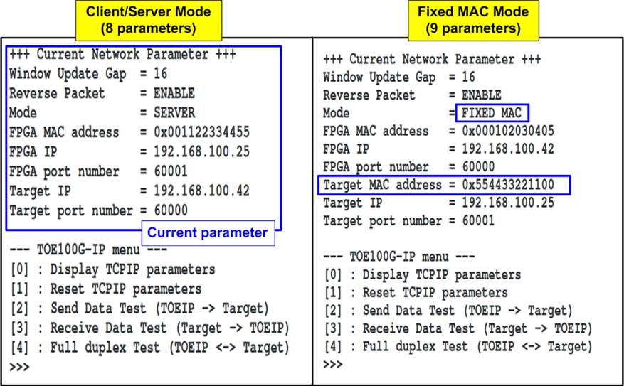
Figure 4‑1 Display current parameter result
1) Window Update Gap: Set threshold value to transmit window update packet. Valid value is 0x00 – 0x3F (0-63). The unit size of threshold value is 1 Kbyte. Default value is 16 (window update packet every 16 Kbytes).
2) Reverse Packet: This flag is enabled to allow the IP sending the retransmitted packet when IP waits Windows update packet returned from the target for long time. Default value is ENABLE.
3) Mode: Set mode to TOE100G-IP to initial in Server, Client, or Fixed MAC. Input ‘0’ for Client, ‘1’ for Server, or ‘2’ for Fixed MAC.
4) FPGA MAC address: 48-bit hex value to be MAC address of Accelerator system. Default value is 0x000102030405 (Client/Fixed MAC mode) or 0x001122334455 (Server mode).
5) FPGA IP: IP address of Accelerator system. Default value is 192.168.100.42 (Client/Fixed mode) or 192.168.100.25 (Server mode).
6) FPGA port number: Port number of Accelerator system. Default value is 60000 (Client/Fixed MAC mode) or 60001 (Server mode).
7) Target MAC address (displayed when running Fixed MAC mode only): 48-bit hex value to be MAC address of the target device. Default value is 0x554433221100.
8) Target IP: IP address of the target device (100 Gb Ethernet on PC). Default value is 192.168.100.25 (Client/Fixed MAC mode) or 192.168.100.42 (Server mode).
9) Target port number: Port number of the destination device to transfer 100 Gb Ethernet data. Default value is 60001 (Client/Fixed MAC mode) or 60000 (Server mode).
To change some parameters, the user runs menu [1] (Reset TCPIP parameters).
4.2 Reset TCPIP parameters
Select ‘1’ to reset the IP and change IP parameters.
This menu is used to change IP parameters or send reset to TOE100G-IP. After user selects this menu, the current parameters are displayed on the console. User enters ‘x’ to use the same parameters while other keys are entered to change some parameters. After the parameters are fixed, reset signal is sent to TOE100G-IP to start the initialization process.
There are eight or nine parameters to set in this menu. Each parameter is verified by software (CPU). The parameter is updated to TOE100G-IP when the input is valid. If which input is not valid, the parameter does not change. After user inputs all parameters, the IP is reset. The description of each parameter is shown in Topic 4.1 (Display TCPIP parameters) and the range of each parameter is described as follows.
Note:
1. The mode on two devices must be set to Server – Client, Client – Fixed MAC, or Fixed MAC – Fixed MAC.
2. When running Server – Client mode and user needs to reset parameters on the Server device, the Client device must be also reset. Also, the Server device must be reset before the Client device to wait until ARP request sent by the Client device.
3. Parameter of two devices must be matched, as following list.
a. Target IP of device#1 = FPGA IP of device#2
b. FPGA IP of device#1 = Target IP of device#2
c. Target port number of device#1 = FPGA port number of device#2
d. FPGA port number of device#1 = Target port number of device#2
1) Mode: Input ‘0’ (Client), ‘1’ (Server), or ‘2’ (Fixed MAC) to determine IP initialization mode.
2) Reverse Packet: Set ‘0’ to disable or ‘1’ to enable this feature.
3) Window Update Gap: Set threshold value to transmit windows update packet. Valid value is 0x00 – 0x3F (0-63). The unit size of threshold value is 1 Kbyte. Default value is 16 (window update packet every 16 Kbytes).
4) FPGA MAC address: Input 12 digits of hex value. Add “0x” as a prefix to input as hex value.
5) FPGA IP address: A set of four decimal digits is separated by “.”. The valid range of each decimal digit is 0-255.
6) FPGA port number: Valid range is 0-65535.
7) Target MAC address (displayed when running Fixed MAC mode only): Input 12 digits of hex value. Add “0x” as a prefix to input as hex value.
8) Target IP address: A set of four decimal digits, similar to FPGA IP address.
9) Target port number: Valid range is 0-65535.
After finishing parameter assignment, the updated parameters are displayed on the console. Next, the reset signal is sent to the IP and then the IP initializes by using new parameters. Finally, “IP initialization complete” is shown after the initialization process is done, as shown in Figure 4‑2 and Figure 4‑3.
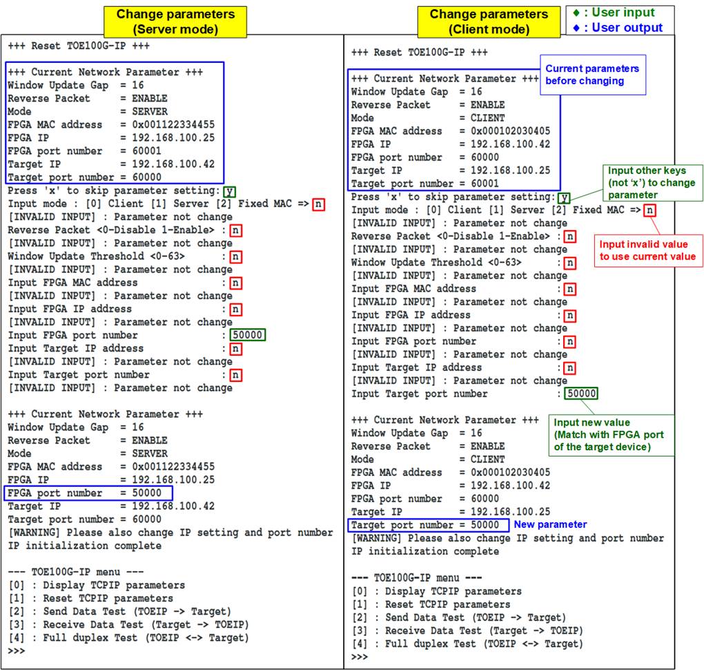
Figure 4‑2 Change IP parameter result for Server and Client mode
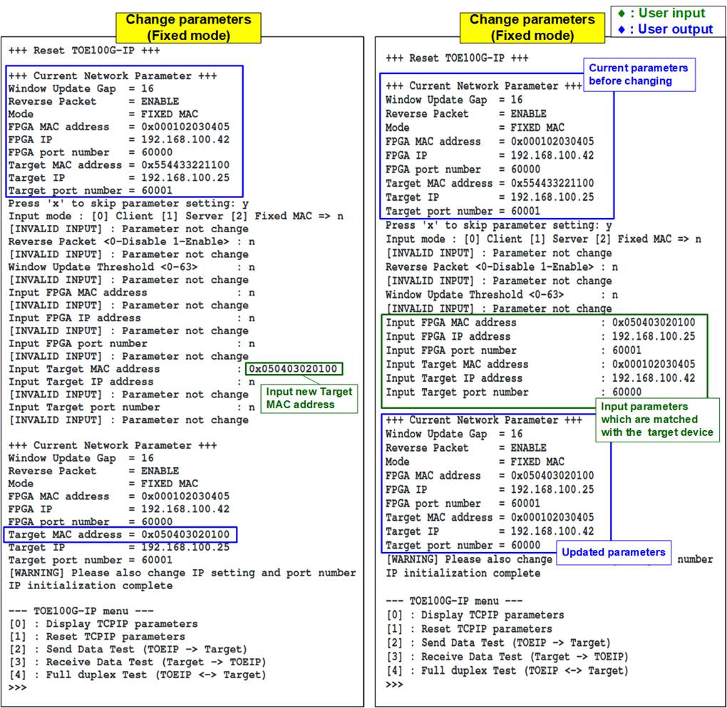
Figure 4‑3 Change IP parameter result for Fixed MAC mode
4.3 Send Data Test (Server to Client)
To transfer data from Server device to Client device, select ‘2’ to run send data test on the Server device and select ‘3’ to run receive data test on the Client device. User inputs test parameters on the consoles. The sequence to run the test is shown as follows.
Note: The mode set in Send data test, Receive data test, and Full duplex test when running by using two Accelerator systems is applied to specify how to open and close the connection. It can be selected to be active mode (Client) or passive mode (Server). It does not relate to the initialization mode which is set to be Client, Server, or Fixed-MAC mode. The connection mode that is set to the two devices must be different, one is Client and another is Server.
1) On Server console, input four parameters in send data test menu.
a) Input transfer size: Unit of transfer size is byte. Valid value is 0x40 - 0x3F_FFFF_FFC0. The input must be aligned to 64. The input is decimal unit when input only digit number. User adds “0x” to be a prefix for hexadecimal unit.
b) Input packet size: Unit of packet size is byte. Valid value is 64 – 8960. The input must be aligned to 64. The input is decimal unit when input only digit number. User adds “0x” to be a prefix for hexadecimal unit.
c) Input data generation mode: Mode of pattern data generation. Set ‘1’ to use 32-bit incremental data or ‘0’ to use null value.
d) Input Mode: The connection mode. Input ‘1’ to open connection by Server mode (Passive open).
2) If inputs are valid, “Wait Open connection …” is displayed to wait until the Client device sends the request for the new connection.
Note: If some inputs are invalid, “Out-of-range input” or “Invalid input” is displayed and then the operation is cancelled, as shown in Figure 3‑6 - Figure 3‑7 (similar to the test with PC).
3) On Client console, input three test parameters in receive data test menu.
a) Input transfer size: Unit of transfer size is byte. Valid value is 0x40 - 0x3F_FFFF_FFC0. The input must be aligned to 64. The input is decimal unit when input only digit number. User adds “0x” to be a prefix for hexadecimal unit. This value must be equal to transfer size that is set on Server device.
b) Input data verification mode: Set ‘0’ to disable data verification or ‘1’ to enable data verification to verify data from the Server device.
c) Input Mode: The connection mode. Input ‘0’ to open connection by Client mode (Active open).
After all inputs are valid, the operation begins.
4) After running the Client device, the port is created. Current transfer size is displayed on both consoles every second. “Send data completed” is displayed after finishing sending all data.
5) The Server device closes the connection. Finally, total transfer size and performance are displayed on both consoles.
Figure 4‑4 shows the example of send data test when using jumbo frame size with pattern data generation. The left window is the Server console while the right window is the Client console. The result shows a significant improvement from the send data test using Test PC as a test environment, comparing with Figure 3‑4.
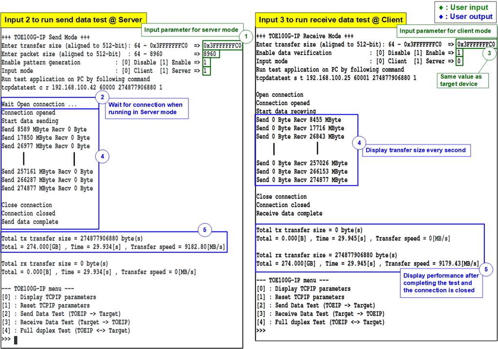
Figure 4‑4 Send data test by using jumbo frame with enabling pattern data generation
Figure 4‑5 shows the example of send data test when using jumbo frame size by using null value. Comparing to Figure 4‑4, the performance of the disabling the pattern data generation is better than the enabling one and achieves nearly to the maximum transfer speed in the 100Gb Ethernet.

Figure 4‑5 Send data test by using jumbo frame with disabling pattern data generation
4.4 Receive Data Test (Client to Server)
To transfer data from Client device to Server device, select ‘3’ to run receive data test on the Server device and select ‘2’ to run send data test on the Client device. User inputs test parameters on the consoles. The sequence to run the test is shown as follows.
1) On Server console, input three parameters in receive data test.
a) Input transfer size: Unit of transfer size is byte. Valid value is 0x40 - 0x3F_FFFF_FFC0. The input must be aligned to 64. The input is decimal unit when input only digit number. User adds “0x” to be a prefix for hexadecimal unit.
b) Input data verification mode: Set ‘0’ to disable data verification or ‘1’ to enable data verification to verify data from the Client device.
c) Input Mode: The connection mode. Input ‘1’ to open connection by Server mode (Passive open).
2) If inputs are valid, “Wait Open connection …” is displayed to wait until the Client device sends the request for the new connection.
3) On Client console, input three test parameters in send data test.
a) Input transfer size: Unit of transfer size is byte. Valid value is 0x40 - 0x3F_FFFF_FFC0. The input must be aligned to 64. The input is decimal unit when input only digit number. User adds “0x” to be a prefix for hexadecimal unit. This value must be equal to transfer size that is set on Server device.
b) Input packet size: Unit of packet size is byte. Valid value is 64 – 8960. The input must be aligned to 64. The input is decimal unit when input only digit number. User adds “0x” to be a prefix for hexadecimal unit.
c) Input data generation mode: Mode of pattern data generation. Set ‘1’ to use 32-bit incremental data or ‘0’ to use null value.
d) Input Mode: The connection mode. Input ‘0’ to open connection by Client mode (Active open).
After all inputs are valid, the operation begins.
4) After running the Client device, the port is created. Current transfer size is displayed on both consoles every second.
5) “Connection closed” and “Received data completed” are displayed on Server console after Client device finishes sending all data and closing the connection. Finally, total transfer size and performance are displayed on both consoles.
Figure 4‑6 shows the example of receive data test when using jumbo frame size with enabling the data verification on the Server device
Figure 4‑7 shows the example of receive data test when using jumbo frame size with disabling the data verification on the Server device. From the both results, it can conclude that running the receive data test can achieve the maximum speed, nearly to the 100Gb Ethernet speed, when disabling the data verification on the Accelerator system.
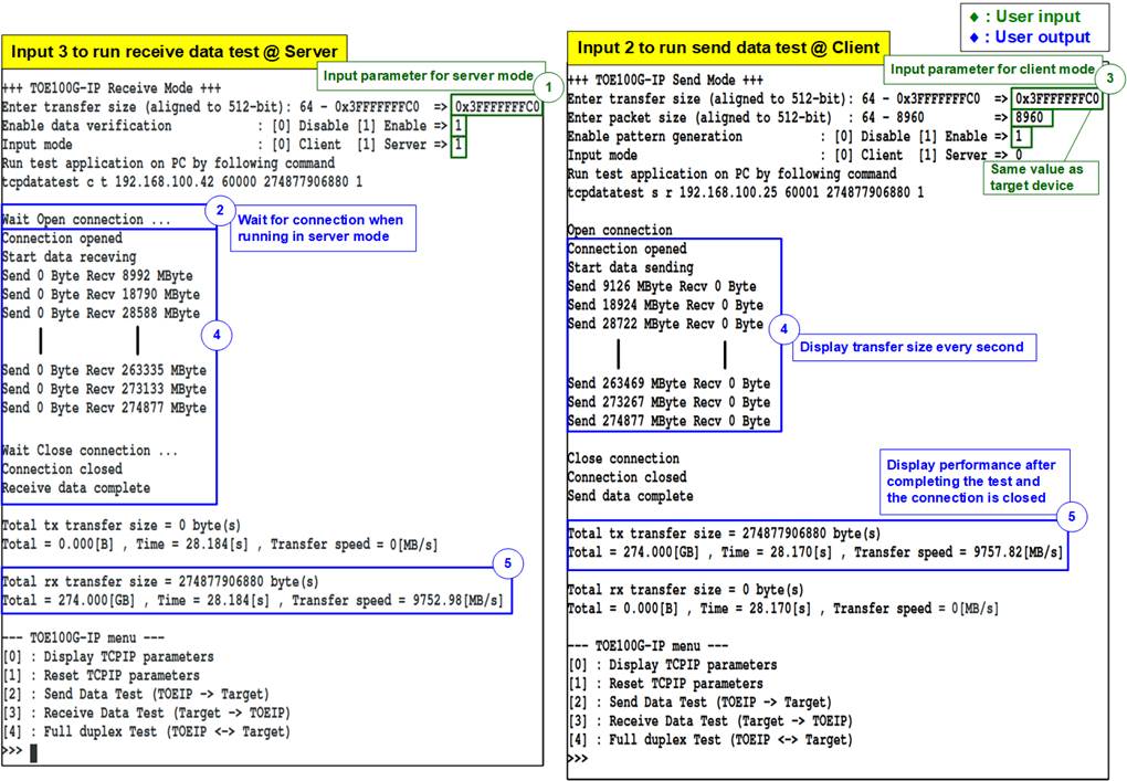
Figure 4‑6 Receive data test with data verification

Figure 4‑7 Receive data test without data verification
4.5 Full duplex Test
Select ‘4’ to run full duplex test on two Accelerator systems to transfer data in both directions at the same time. User inputs test parameters on consoles. The sequence to run the test is shown as below.
1) On Server console, input four parameters in full duplex test.
a) Input transfer size: Unit of transfer size is byte. Valid value is 0x40 - 0x3F_FFFF_FFC0. The input must be aligned to 64 and must match with transfer size that is set to the Client device. The input is decimal unit when input only digit number. User adds “0x” to be a prefix for hexadecimal unit.
b) Input packet size: Unit of packet size is byte. Valid value is 64 – 8960. The input must be aligned to 64. The input is decimal unit when input only digit number. User adds “0x” to be a prefix for hexadecimal unit.
c) Input data verification/generation mode: Set ‘0’ to disable data verification or ‘1’ to enable data verification and pattern data generation.
d) Input Mode: The connection mode. Input ‘1’ to open connection by Server mode (Passive open).
2) If all inputs are valid, “Wait open connection…” is displayed to wait until the Client device sends the request for the new connection.
Note: If some inputs are invalid, “Out-of-range input” or “Invalid input” is displayed and then the operation is cancelled, as shown in Figure 3‑6 - Figure 3‑7 (similar to the test with PC).
3) On Client console, input four test parameters in full duplex test.
a) Input transfer size: Unit of transfer size is byte. Valid value is 0x40 - 0x3F_FFFF_FFC0. The input must be aligned to 64 and must match with transfer size in the Accelerator system that is running as Server. The input is decimal unit when input only digit number. User adds “0x” to be a prefix for hexadecimal unit.
b) Input packet size: Unit of packet size is byte. Valid value is 64 – 8960. The input must be aligned to 64. The input is decimal unit when input only digit number. User adds “0x” to be a prefix for hexadecimal unit.
c) Input data verification/generation mode: Set ‘0’ to disable data verification or ‘1’ to enable data verification and pattern data generation.
d) Input Mode: The connection mode. Input ‘0’ to open connection by Client mode (Active open).
After all inputs are valid, the operation begins.
4) After running the Client device, the port is created. Current transfer size is displayed on both consoles every second.
5) The Client device closes the connection after transferring the data in both directions. Finally, total transfer size and performance are displayed on both consoles.
There are two-second time gap after step 5) for user to stop the operation by pressing any keys on both consoles. Otherwise, repeat step 4) – 5) as forever loop.
Figure 4‑8 shows full duplex test with enabling the data verification on both sides and also enabling the pattern data generation on the Accelerator system. The left window is console from the Accelerator system running as Server and the right window is console from the Client. device
Figure 4‑9 shows full duplex test with disabling the data verification on both sides and also disabling the pattern data generation on the Accelerator system. Comparing to Figure 4‑8, the result shows the performance is increased when running by disabling the data verification and generation.

Figure 4‑8 Full duplex test with data verification/generation

Figure 4‑9 Full duplex test without data verification/generation
5 Revision History
|
Revision |
Date |
Description |
|
1.0 |
20-Sep-22 |
Initial version release |