FPGA setup for TOE/UDP100G-IP with CPU Demo
Rev3.2 27-Jul-23
2 Test environment setup when using FPGA and PC
3 Test environment setup when using two FPGAs.
1 Overview
This document provides a guide on setting up an FPGA board and preparing the necessary test environment to run the TOE100G-IP/UDP100G-IP demo or multi-session demo. The user has the option to create two test environments for transferring TCP/UDP payload data via a 100G Ethernet connection using either TOE100G-IP or UDP100G-IP. Figure 1‑1 illustrates these two options.
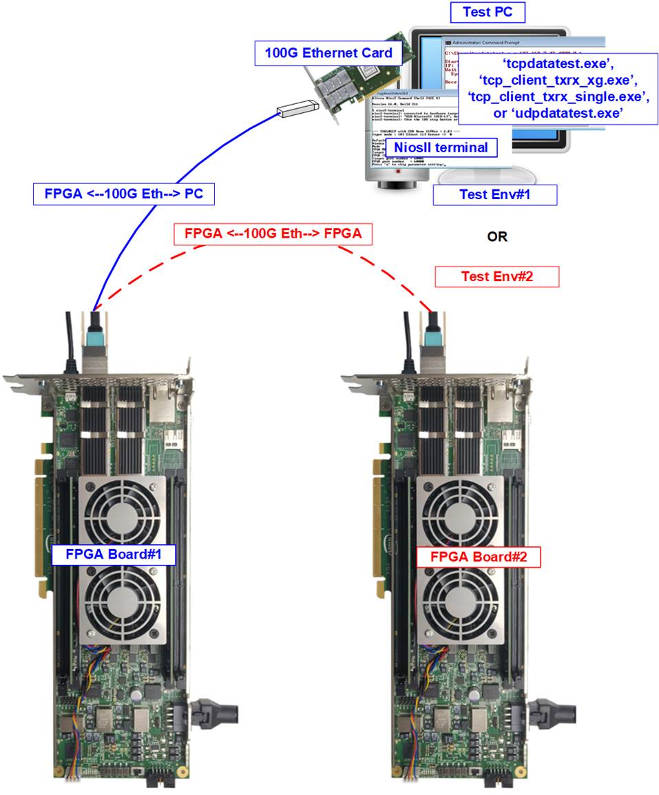
Figure 1‑1 Two test environments for running the demo
The first test environment requires one FPGA board and a PC with a 100G Ethernet card for data transfer. The PC runs a test application, such as “tcpdatatest” (half-duplex test for TOE100G-IP), “tcp_client_txrx_xg” (full-duplex test for TOE100G-IP), “tcp_client_txrx_single” (full-duplex test for multisession TOE100G-IP), or “udpdatatest” (test application for UDP100G-IP). The NiosII Terminal is also run on the PC to act as the user interface console.
The second test environment involves two FPGA boards which may be different from each other. Both boards run the TOE100G-IP, multi-session of TOE100G-IP, or UDP100G-IP demo, with different initialization mode assigned (Client, Server, or Fixed-MAC).
The demo is implemented on multiple FPGA boards, each with different settings for RS-FEC features. For specific information of the RS-FEC settings one ach FPGA board, please refer to the table provided below.
Table 1‑1 The features of RS-FEC for TOE100G-IP/UDP100G-IP demo on each board
|
Board name |
RS-FEC feature |
|
TOE100G-IP demo |
|
|
Stratix10 MX |
Disabled |
|
Stratix10 TX ES (Rev.A) |
Enabled |
|
Stratix10 TX (Rev.B) |
Enabled |
|
Agilex 7 F-series |
Enabled |
|
UDP100G-IP demo |
|
|
Agilex 7 F-series |
Disabled |
2 Test environment setup when using FPGA and PC
Before running the demo using an FPGA and PC, please prepare the following.
- FPGA development boards: Stratix10 MX, Stratix 10 TX, Stratix 10 TX ES, and Agilex 7 F-series development kits
- PC with a 100 Gigabit Ethernet card
- 100G Ethernet cable: 2xQSFP28 transceivers and MPO-to-MPO cable
- USB cable connecting between FPGA and PC for JTAG connection
a) A micro USB cable: Stratix10 MX development kit and Agilex F-series development kit
b) A USB type-B cable: Stratix 10 TX and Stratix 10 TX ES development kit
- Test application provided by Design Gateway for running on PC
a) TOE25G-IP: “tcpdatatest.exe” and “tcp_client_txrx_xg.exe”
b) Multi-session of TOE25G-IP: “tcpdatatest.exe” and “tcp_client_txrx_single.exe”
c) UDP25G-IP: “udpdatatest.exe”
- Quartus Programmer and NiosII command shell, installed on PC
Note: The hardware listed below is an example for running the demo.
[1] 100G Network Adapter: NVIDIA MCX614106A-CCAT ConnectX-6 Ethernet Adapter Card
https://www.colfaxdirect.com/store/pc/viewPrd.asp?idproduct=3767&idcategory=0
[2] QSFP28 Transceiver (100GBASE-SR4)
https://www.sfpcables.com/100gbase-sr4-qsfp28-transceiver-for-mmf-70-100-meters-mpo-mtp-4813
[3] MPO to MPO cable: OM4-MPO-8MPO-1M
https://www.sfpcables.com/mpo-to-mpo-multimode-om4-50-125-m-8-core-4381
[4] Test PC:
Motherboard: Gigabyte Z590 AORUS MASTER (rev. 1.0)
CPU: Intel i7-11700K CPU 3.6 GHz
RAM: 32 GB DDR4
OS: 64-bit Windows10 OS
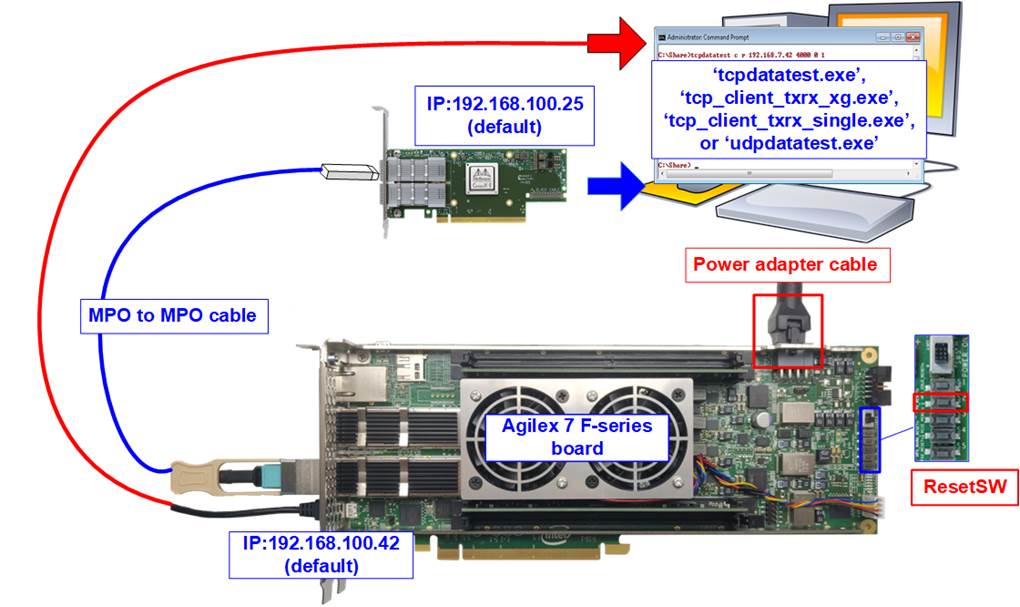
Figure 2‑1 TOE100G-IP/UDP100G-IP with CPU demo (FPGA<->PC) on Agilex F-series
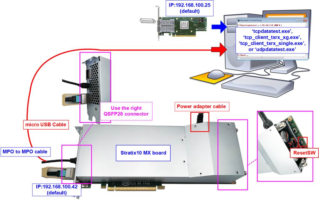
Figure 2‑2 TOE100G-IP/UDP100G-IP with CPU demo (FPGA<->PC) on Stratix10 MX
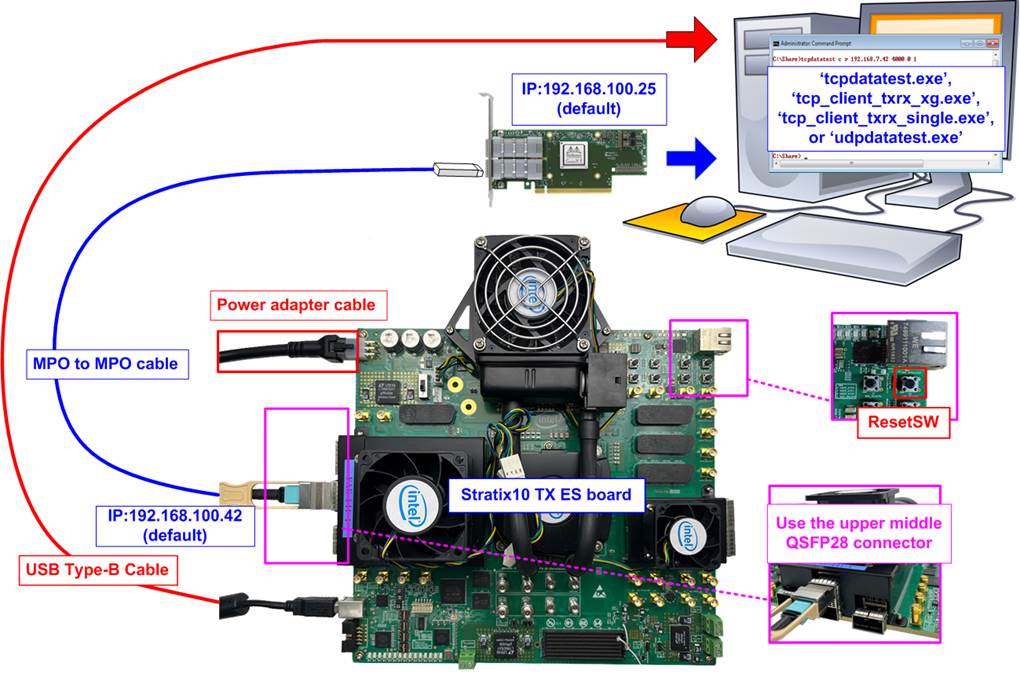
Figure 2‑3 TOE100G-IP/UDP100G-IP with CPU demo (FPGA<->PC) on Stratix10 TX ES (Rev.A)
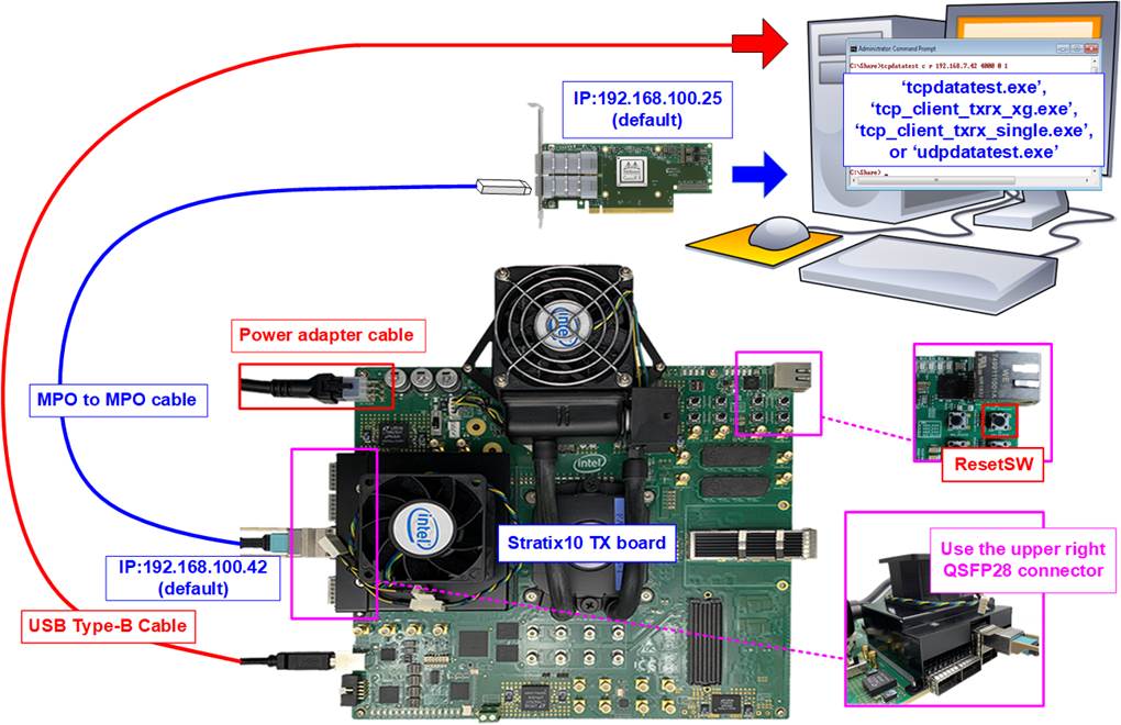
Figure 2‑4 TOE100G-IP/UDP100G-IP with CPU demo (FPGA<->PC) on Stratix10 TX (Rev.B)
The steps for setting up a test environment using an FPGA board and a PC are described below.
1) Turn off power switch and connect the power supply to the FPGA board.
2) Connect a micro USB cable or a USB type-B cable from the FPGA board to the PC for JTAG programming and JTAG UART.
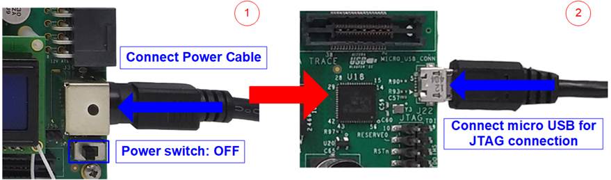
Figure 2‑5 Power connection and microUSB connection
3) Establish a connection between the FPGA board and the PC by connecting a 100G Ethernet cable. Insert two QSFP28 with MPO to MPO cable between the FPGA board and the PC, as shown in Figure 2‑6.
· S10MX and Agilex 7 F-series boards: There are two QSFP28 connectors available. Use the right connector.
· S10TX ES (Rev.A) and S10TX (Rev.B) boards: There are five QSPF28 connectors at the power cable side available. Use the upper connector.
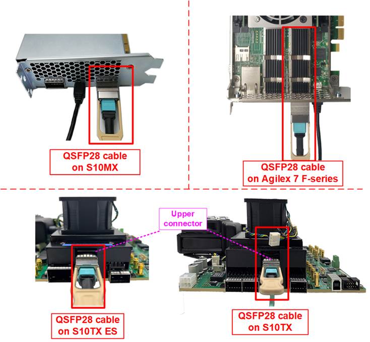
Figure 2‑6 100G Ethernet connection
4) Please ensure the DIPSW of the specific boards is correct, described as follows.
a) For Agilex F-series board, please check SW1 which is placed at the bottom side of the board. The setting of bit[1]-[3] must be OFF OFF OFF to configure FPGA by using JTAG only.
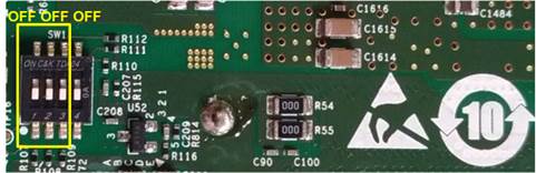
Figure 2‑7 SW1 setting on Agilex F-series board
b) For Stratix10 TX and Stratix 10TX ES board, please verify SW6 to ensure that bit[0] is set to OFF. This configuration is necessary to enable the Ethernet connection of the FPGA, which operates using the reference clock from the programmable clock on the board.
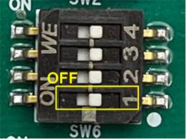
Figure 2‑8 SW6 setting of Stratix10 TX(ES) board
5) Turn on the power switch on the FPGA board.
6) Ensure that the reference clock value is configured correctly.
· S10MX board: Set clock frequency of Si5341A(OUT0) to 644.53125 MHz.
· S10TX and S10TX ES: Set clock frequency of Si549 to 156.25 MHz.
· Agilex 7 F-series board: Set clock frequency of Si5341(OUT0) to 156.25 MHz.
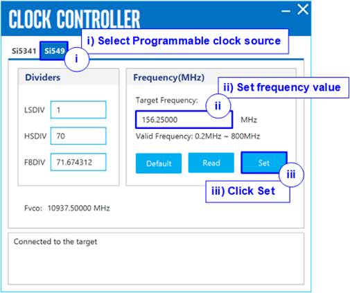
Figure 2‑9 Set Clock source of S10TX and S10TX ES
7) Open Quartus Programmer and follow these steps to program the FPGA via USB-1.
i) Click on “Hardware Setup…” and select USB-BlasterII[USB-1].
ii) Click on “Auto Detect” and select the FPGA number.
iii) Select the FPGA device icon.
iv) Click on the “Change File” button, choose the SOF file in the pop-up window, and click “open” button.
v) Check the “Program” option.
vi) Click on the “Start” button to program the FPGA.
vii) Wait until the Progress status reaches 100%.
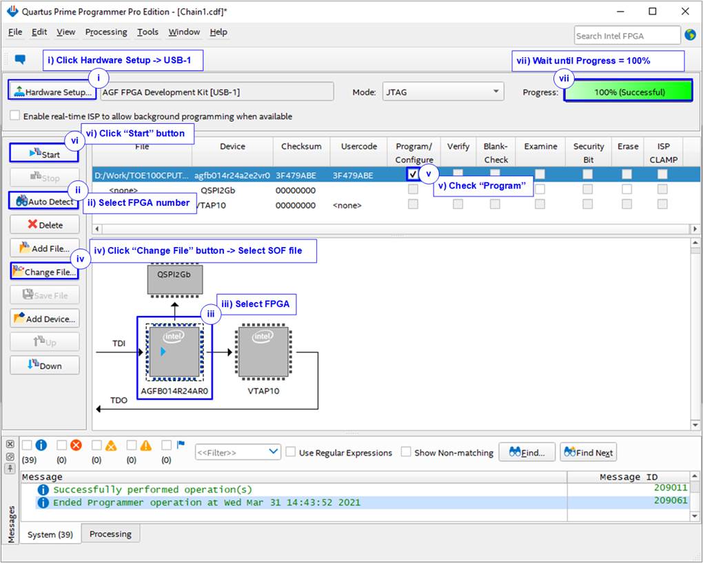
Figure 2‑10 FPGA Programmer
8) Open the NiosII command shell.
i) Type “nios2-terminal” to launch the console.
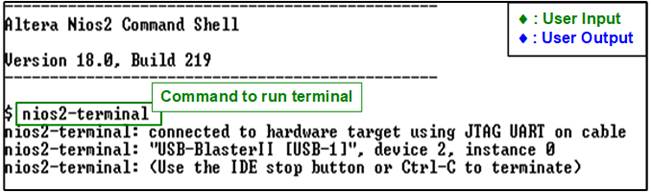
Figure 2‑11 Run NiosII terminal
ii) Enter ‘0’ to initiate TOE100G-IP/UDP100G-IP initialization in Client mode (which will send an ARP request to retrieve the PC MAC address).
iii) The default parameter for the Client mode will be displayed on the console.
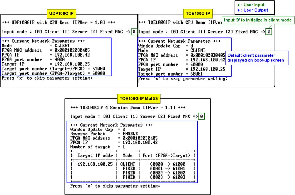
Figure 2‑12 Message after system boot-up
However, if there is an Ethernet connection problem and the status is linked down, an error message will be displayed instead of the welcome message, as shown in Figure 2‑13.
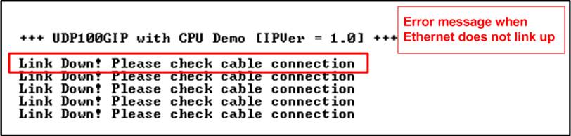
Figure 2‑13 Error message when cable is linked down
iv) If the user wishes to skip parameter setting and use default parameters to start the system initialization, input ‘x’ as shown in Figure 2‑14. If any other keys are entered, the menu for changing parameter will appear, similar to the “Reset TCPIP/UDPIP parameters” menu. The examples of running the main menu of TOE100G-IP, Multisession of TOE100G-IP, and UDP100G-IP are described in
“dg_toe100gip_cpu_instruction”, “dg_toe100gip_4ss_instruction”, and
“dg_udp100gip_instruction” documents, respectively.
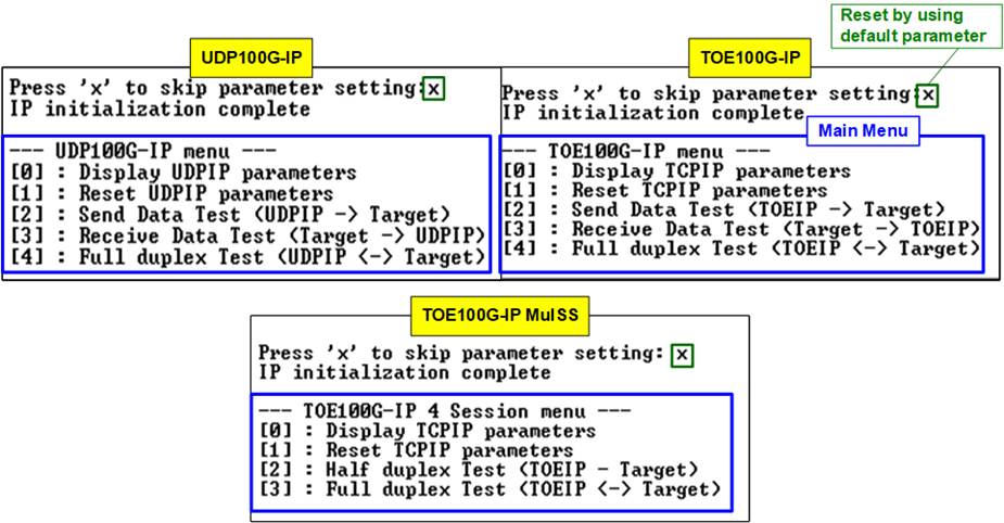
Figure 2‑14 Initialization complete
Note: Transfer performance in the demo is limited by the PC performance. The best performance can be achieved when the test is run using FPGA-to-FPGA connection.
3 Test environment setup when using two FPGAs
Before running the test, please prepare following test environment.
- Two FPGA development boards, which can be either the same or different boards:
Stratix10 MX, Stratix 10 TX, Stratix 10 TX ES, and Agilex 7 F-series development kits
- 100G Ethernet cable: 2xQSFP28 transceivers and MPO-to-MPO cable
- USB cable connecting a FPGA board to PC for JTAG connection
a) Micro USB cable: Stratix10 MX and Agilex 7 F-series development kits
b) USB type-B cable: Stratix 10 TX and Stratix 10TX ES development kit
- Quartus Programmer for programming the FPGA and NiosII command shell, installed on PC
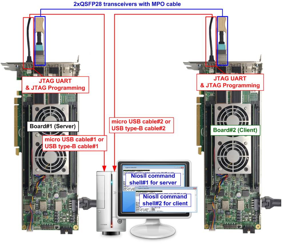
Figure 3‑1 TOE100G-IP/UDP100G-IP with CPU demo (FPGA<->FPGA)
The steps for setting up a test environment using two FPGAs are described below.
To get started with the demo, follow steps 1) – 6) of topic 2 (Test environment setup when using FPGA and PC) to set up the FPGA board and QSFP28 connection. Once you have completed the configuration for two FPGA boards, a menu will be displayed on the console for selecting Client mode, Server mode, or Fixed MAC mode. Follow the detailed steps below to continue the demo.
Note: When connecting two FPGA boards to the same PC via USB cable simultaneously, the Quartus programmer will detect two USB-BlasterII hardware devices, namely USB-1 and USB-2. Choose the appropriate USB channel and start programming the configuration file to first board. Once the first board programming is completed, switch the USB channel and program the configuration file to the second board.
Figure 3‑2 Two USB-Blaster cables when connecting two FPGA boards to PC
1) Open NiosII Command Shell.
i) Run nios2-terminal –cable 1 command for FPGA#1
ii) Run nios2-terminal –cable 2 command for FPGA#2
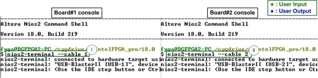
Figure 3‑3 Run NiosII terminal on two consoles
2) Enter the input to initialize in Server/Client/Fixed-MAC mode. An example to initialize by Server-Client mode is below.
i) Set ‘1’ on console of FPGA board#1 for running in Server mode.
ii) Set ‘0’ on console of FPGA board#2 for running in Client mode.
iii) The default parameters for the selected mode will be displayed on the console, as shown in Figure 3‑4.
Note: The rules for setting the initialization mode are below.
· If the first board is initialized in Server mode, the other board must be initialized in Client mode.
· If the first board is initialized in Fixed MAC mode, the other board can be run in Client mode or Fixed MAC mode.
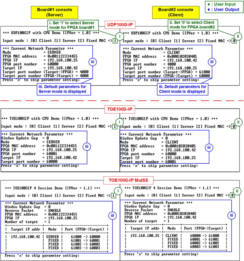
Figure 3‑4 Input mode
3) Input ‘x’ to use default parameters or use other keys to change parameters. The parameters of Server mode must be set before Client mode. The details are divided into two parts, running the TOE100G-IP demo and running the UDP100G-IP demo.
When running single-session or multi-session of TOE100G-IP,
i) Set parameters on the Server console (board#1 console).
ii) Set parameters on the Client console (board#2 console) to start IP initialization by transferring ARP packet.
iii) After finishing the initialization process, “IP initialization complete” and the main menu are displayed on the Server and Client consoles.
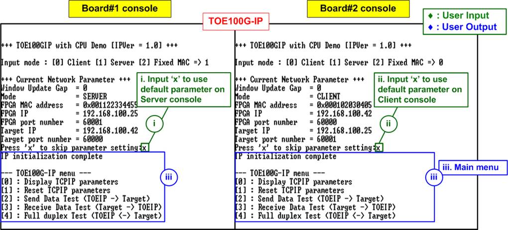
Figure 3‑5 Main menu of TOE100G-IP (Single-session)
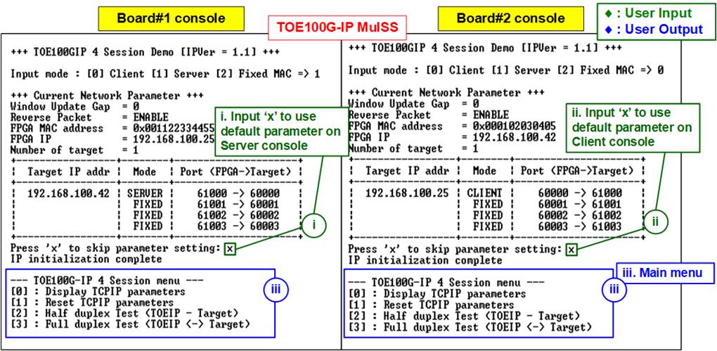
Figure 3‑6 Main menu of TOE100G-IP (Multi-session)
When running UDP100G-IP,
i) For Server mode (board#1 console), if user does not change the default parameters, input ‘x’ to skip parameter setting.
ii) For Client mode, the user must change Target port number (Target->FPGA) to use same value as Target port number (FPGA->Target).
iii) After finishing initialization process, “IP initialization complete” and the main menu will be displayed on the Server and Client consoles.
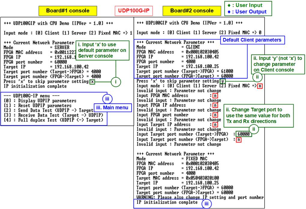
Figure 3‑7 Main menu of UDP100G-IP
4 Revision History
|
Revision |
Date |
Description |
|
3.2 |
27-Jul-23 |
Support S10TX ES (Rev.A) and add clock controller setting |
|
3.1 |
25-May-23 |
1) Update full-duplex test application from “tcp_client_txrx_40G” to “tcp_client_txrx_xg”. 2) Add RS-FEC feature lists on each demo |
|
3.0 |
11-Mar-22 |
Add multi-session demo |
|
2.0 |
18-Aug-21 |
Add UDP100G-IP |
|
1.0 |
19-Apr-21 |
Initial release |