FPGA Setup for TOE/UDP10G-IP with CPU Demo
1 Overview
This document provides guidance on setting up an FPGA board and preparing the required test environment to run a demonstration of Design Gateway’s TCP and UDP offloading IP cores over a 10-Gigabit Ethernet connection.
The reference design supports a single connection to one target device. The target device can be either:
· A PC equipped with a 10-Gigabit Ethernet interface, which provides a flexible and fully functional test environment, or
· Another FPGA board integrating Design Gateway’s TCP and UDP offloading IP cores, enabling high-performance data transfers at the full 10-Gigabit Ethernet bandwidth.
These configurations allow users to evaluate the IP cores across a range of scenarios, from practical PC-based testing to high-throughput FPGA-to-FPGA communication, as illustrated in Figure 1.

Figure 1 Test Environment for the Demo
To support PC-based target testing, Design Gateway provides the following software applications:
· tcpdatatest (half-duplex test for TCP IP cores)
· tcp_client_txrx_xg (full-duplex test for TCP IP cores)
· udpdatatest (test application for UDP IP cores)
When a PC is used as the target device, data transfer performance may be limited by the PC’s hardware resources. In contrast, FPGA-to-FPGA communication can demonstrate the full performance capabilities of the Design Gateway IP cores.
A PC equipped with Serial console software and FPGA programming tools is required to connect to the FPGA-based host via USB for test configuration and status monitoring. This PC can also serve as the PC-based target device.
2 Test Environment Setup
The demo requires at least one FPGA-based system to act as the host. The target system can be either PC-based or FPGA-based. This section outlines the hardware requirements and setup procedures for running the demo.
2.1 Hardware List
To run the demo, both the host and target systems must support 10G Ethernet connectivity. The following list provides example hardware requirements for each system type.
FPGA-Based System (Host or Target)
1) FPGA board or card: ZC706, ZCU102, ZCU106, KCU105, VCU118, KCU116, ZCU111, VCK190, AUBoard 15P, Alveo X3522.
2) 10G Ethernet connectivity:
· VCU118 or VCK190: QSFP+ to four SFP+ breakout cable
· Other boards or cards: SFP+ to SFP+ cable, which can be one of the following:
- 10G SFP+ Passive Direct Attach Cable (DAC), with a length of 1 meter or less
- 10G SFP+ Active Optical Cable (AOC)
- Two 10G SFP+ optical transceivers (10GBASE-R) with a multimode LC-to-LC optical cable
3) Programming and Serial console connections between FPGA and PC:
· ZCU102, ZCU106, KCU105, VCU118 and KCU116: Two micro-USB cables, one for FPGA programming and one for the Serial console.
· ZC706: One mini-USB cable for FPGA programming and one micro-USB cable for the Serial console
· ZCU111, AUBoard 15P: One micro-USB cable for both FPGA programming and the Serial console.
· VCK190: One USB Type-C cable for both FPGA programming and Serial console.
· Alveo X3522 card: Alveo Debug Kit (ADK2) with a micro-USB cable for both FPGA programming and Serial console.

Figure 2 ZC706-Based System
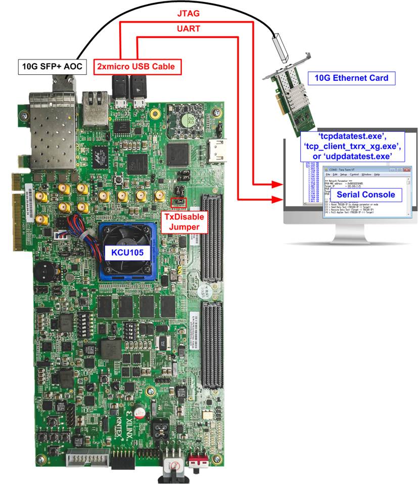
Figure 3 KCU105-Based System

Figure 4 KCU116-Based System
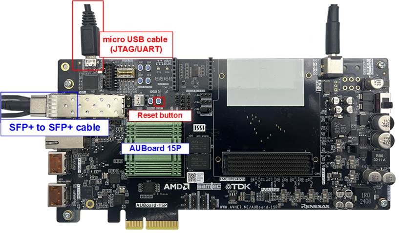
Figure 5 AUBoard 15P-Based System

Figure 6 ZCU102-Based System
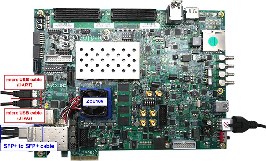
Figure 7 ZCU106-Based System
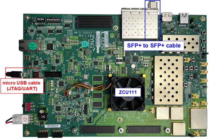
Figure 8 ZCU111-Based System
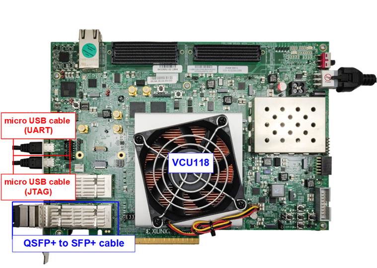
Figure 9 VCU118-Based System
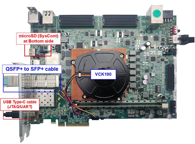
Figure 10 VCK190-Based System
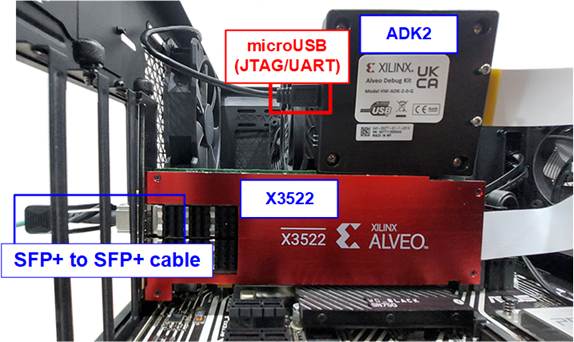
Figure 11 Alveo X3522-Based System
PC-Based Target System
1) PC equipped with a 10 Gigabit Ethernet adapter
2) 10G Ethernet connectivity: QSFP+ to four SFP+ breakout cable or SFP+ to SFP+ cable
3) Test applications provided by Design Gateway:
· “tcpdatatest.exe” (for TCP half-duplex testing)
· “tcp_client_txrx_xg.exe” (for TCP full-duplex testing)
· “udpdatatest.exe” (for UDP testing)
4) If the same PC is used to control the host FPGA, it must also have:
· Vivado Tools for FPGA programming
· Serial console application (e.g., TeraTerm) with the following settings: Baud rate=115,200; Data=8-bit; Parity=None; and Stop bits=1-bit
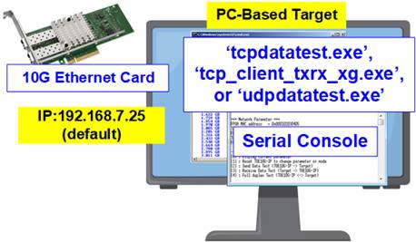
Figure 12 PC-Based Target System
Note: Below is an example configuration used to run the demo successfully:
· 10G Network Adapter: Nvidia MCX631102AC-ADAT
· Ethernet Cable Options:
- 10-Gigabit SFP+ AOC cable (AOC-S1S1-001)
https://www.10gtek.com/10gsfp+aoc
- 40-Gigabit QSFP to 4x10-Gigabit SFP+ cable
https://www.digikey.sg/htmldatasheets/production/1756903/0/0/1/fcbn510qe2cxx-preliminary.html
· PC Specification:
Motherboard : ASUS PRIME Z690M-Plus D4
CPU : Intel i5-12600K CPU 3.7 GHz
RAM : 64 GB DDR4
OS : 64-bit Windows 10
2.2 FPGA Setup
The following steps describe how to set up an FPGA board/card to run the demo.
1) Check the DIPSW and jumper settings on the FPGA board.
· For ZC706 board: The board setting is shown in Figure 13.
i) Insert jumper to J17 to enable Tx SFP+.
ii) Set SW11 to configure PS from JTAG.
iii) Set SW4 to use USB-JTAG.
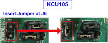
Figure 13 ZC706 Board Setting
· For ZCU102/ZCU106/ZCU111 boards: The board setting is shown in Figure 14.
i) Set SW6=all ONs to use USB-JTAG.
ii) Only ZCU102, insert jumper to J16 to enable Tx SFP+.

Figure 14 ZCU102/ZCU106/ZCU111 Board Setting
· For KCU105 board: The board setting is shown in Figure 15. Insert jumper to J6 to enable Tx SFP+.

Figure 15 Jumper for Enabling SFP+ on KCU105
2) Connect USB cables between FPGA board/card and PC for JTAG programming and Serial console.
· ZC102, ZCU106, KCU105, VCU118, KCU116 boards: Use two micro-USB cables.
· ZC706 board: Use a mini USB cable and a micro USB cable.
· ZCU111, AUBoard 15P: Use a micro-USB cable.
· VCK190 board: Use a type-C USB cable.
· Alveo X3522 card: Connect the Flex cable from the Alveo accelerator card to the Alveo Debug kit (ADK2). Ensure the Flex cable is firmly connected. And use a micro-USB cable to connect to ADK2.

Figure 16 Flex Cable Connection on X3522
3) Connect power supply to FPGA board/card.
4) Connect 10G Ethernet cable between FPGA board and PC.
· VCU118, VCK190: Insert QSFP+ to 4 SFP+ cable between the FPGA board and the PC. Use SFP+ no.1 to connect to QSFP(1), connector on the right side, as shown in Figure 17.
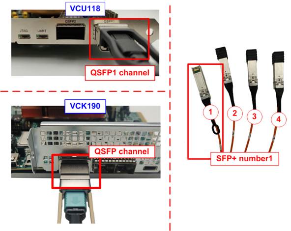
Figure 17 QSFP+ Channel on FPGA Boards
· Others: Insert a 10G SFP+ DAC (Length<1m), AOC, or SFP+ transceiver with an LC-LC cable. Some boards have multiple SFP connectors, so use the appropriate channel as shown in Figure 18.
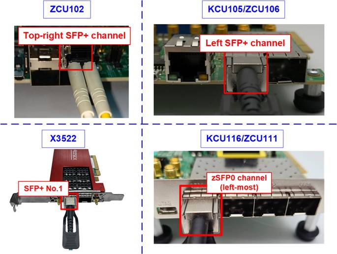
Figure 18 SFP+ Channel on FPGA Board/Card
5) Power on the FPGA board.
For VCK190 board, ensure that the board boots from the SD card to launch the BEAM tool. Booting with a configuration other than the BEAM tool may cause issues with the clock programming functionality in the Board User Interface, which is required in the next step. Follow these steps to boot the VCK190 board to launch the BEAM tool.
i) Ensure the SD card contains the Linux Prebuilt images for the VCK190, officially released by AMD Xilinx, available at https://xilinx-wiki.atlassian.net/wiki/spaces/A/pages/18842316/Linux+Prebuilt+Images
If the SD card does not have the correct image, update it by following the guidance in the section “Installing the System Controller Image” in UG1573: https://docs.amd.com/r/en-US/VCK190/VMK180-Board-Evaluation-and-Management-BEAM-Tool-User-Guide-UG1573/Installing-the-System-Controller-Image
ii) Insert the micro SD card into the system controller’s SD card socket (J206) and set the DIP switch (SW11) to ON OFF OFF OFF to boot from the SysCont SD, as shown in Figure 19.
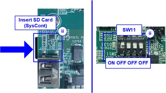
Figure 19 SD Card Boot Setting on VCK190
iii) Connect the VCK190 board to the PC using a USB cable. The PC should recognize three USB Serial Ports. Use the third port to monitor the board boot-up message.
iv) Open a Serial console and connect to the third USB Serial port with following settings: Baud rate=115,200; Data=8-bit; Parity=None; Stop bits=1-bit.
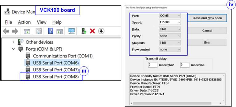
Figure 20 Serial Console Setting
for VCK190
v) Power on the board and monitor the boot-up message on the console. Upon board boot-up completion, close this console to avoid port collision in future steps.
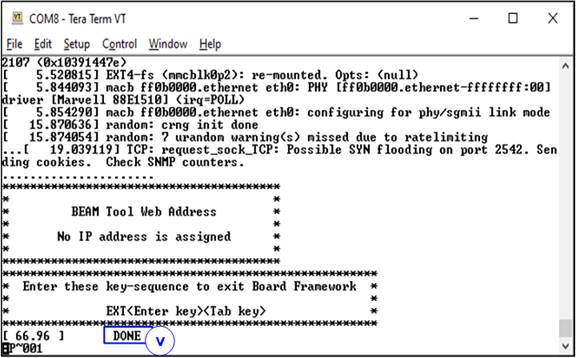
Figure 21 Boot-up Completion Message for VCK190
6) To configure the programmable clock for the FPGA board/card, determine whether your board requires a programmable clock setup. If the board has already used the desired clock frequency, you do not need to re-configure it.
· For KCU116 board: Use “KCU116 – Board User Interface” application to set the programmable clock to 156.25 MHz, as shown in Figure 22.
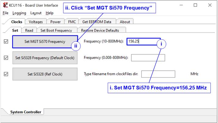
Figure 22 Reference Clock Programming for KCU116
· For VCK190 board: Use “VCK190 – Board User Interface” application to set the programmable clock to 322.265625 MHz, as shown in Figure 23.
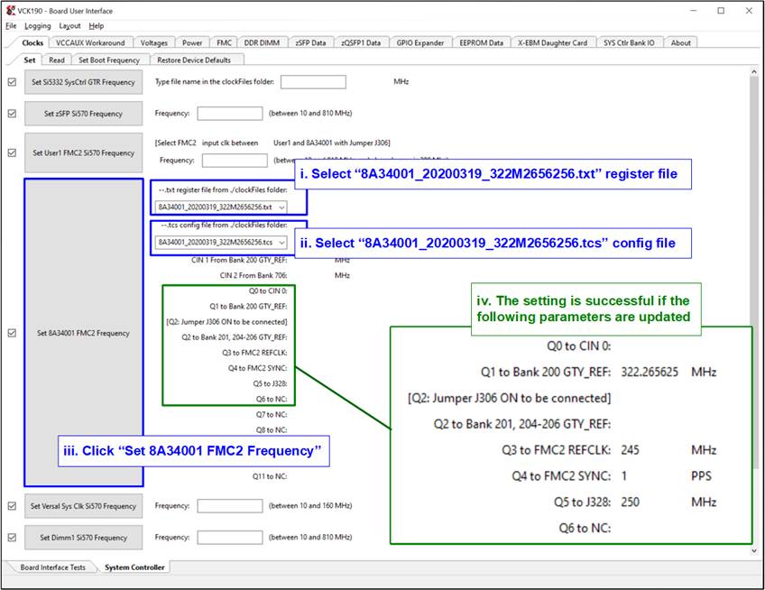
Figure 23 Reference Clock Programming for VCK190
7) Open the Serial console. When the FPGA board is connected to the PC, multiple COM ports from the FPGA connection are detected and displayed in the Device Manager.
· KCU105, VCU118, KCU116: Select the Standard COM port.
· ZCU102, ZCU106: Select the COM port number of Interface0.
· ZCU111, VCK190: Select the lowest value of USB Serial port.
· Alveo X3522: Select the second-lowest value of USB Serial port.
Use the following settings on the Serial console: Baud rate=115,200; Data=8-bit; Parity=None; Stop bits=1-bit.
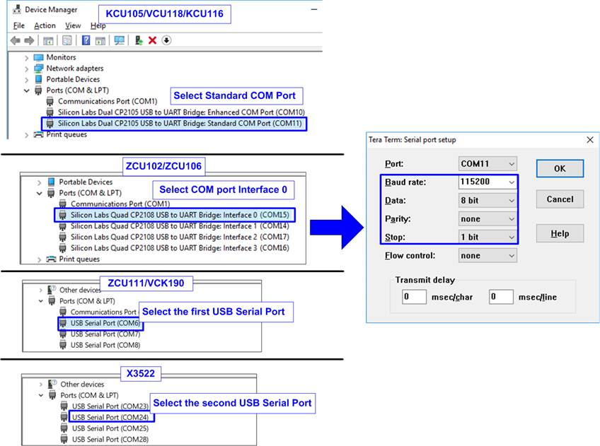
Figure 24 COM Port Number for Serial Console
8) Download configuration file and firmware to the FPGA board.
· SoC boards (ZCU102, ZCU106, ZC706, ZCU111, VCK190): Open the Vivado TCL shell and change the current directory to the download folder that contains the demo configuration file. Type “<ip>10cputest_<board>.bat”, as shown in Figure 25.
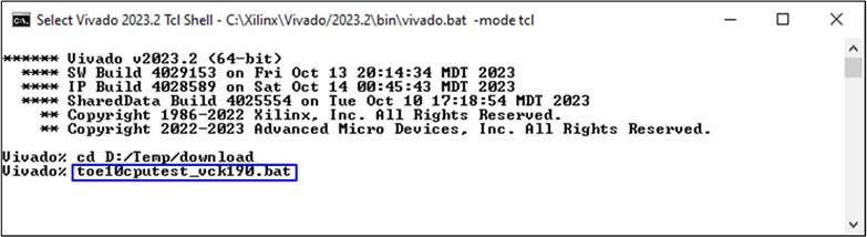
Figure 25 Download File Command script for SoC boards using Vivado Tcl Shell
· Others: Use the Vivado programming to download the configuration file, as shown in Figure 26.

Figure 26 FPGA Configuration using Vivado Device Programmer
3 FPGA Initialization
This section describes the sequence to initialize the host system on FPGA until the connection with the target is successfully established.
1) Launch the Serial console, and a welcome message is displayed showing the demo name and IP core version. The demo then waits for the Ethernet link to be established.
If the Ethernet link is down, a status message is displayed every 5 seconds, as shown in Figure 28. Once the link is up, the user is prompted to configure the local host parameters. This step is the first step of the TCP or UDP IP core initialization process, as shown in Figure 27.
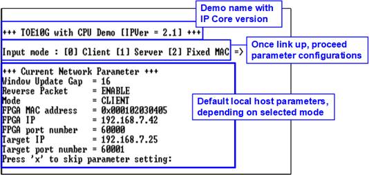
Figure 27 Message after System Boot
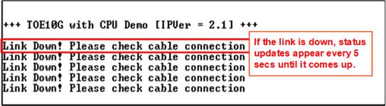
Figure 28 Error Message from Lost Ethernet Connection
To access the main menu, both the local host FPGA and the target device must be initialized using appropriate initialization modes. The rules for setting initialization modes are as follows:
· If the host FPGA and the target device are on the same network, three initialization modes can be used: Server <-> Client, Fixed-MAC <-> Fixed-MAC, and Fixed-MAC <-> Client. For a PC-based target, it is recommended to configure the host FPGA in Client mode.
· If the host FPGA and the target device are on different networks, only Fixed-MAC mode is supported. In this case, the target MAC address must be set to the gateway’s MAC address.
This document presents two example setups: host FPGA <-> target PC and host FPGA <-> target FPGA. In both cases, the host FPGA is configured in Client mode to send an ARP request, and the target is configured in Server mode to respond with an ARP reply.
2) Select the initialization mode on the FPGA console.
PC-Based Target System
i) Enter ‘0’ to initialize the IP core in Client mode. The default Client-mode parameters are then displayed on the Serial console.
ii) Enter ‘x’ to use default parameters for system initialization, or enter any other key to modify the parameters. The parameter update steps correspond to “Menu[1]: Reset IP parameters”. Detailed descriptions of this submenu are provided in the “Demo Instruction Document”.
iii) Once the host successfully communicates with the target using the configured parameters, the message “IP initialization complete”, followed by the main menu, as shown in Figure 29.
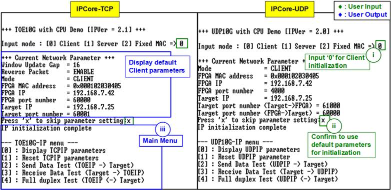
Figure 29 PC-Based Target Initialization
FPGA-Based Target System
i) To initialize the system in Server <-> Client mode, the Server mode must be initialized first by entering ‘1’ on the console. The default Server-mode parameters are then displayed.
ii) Enter ‘x’ to use default parameters for system initialization, or enter any other key to modify the parameters. The parameter update steps correspond to “Menu[1]: Reset IP parameters”. Detailed descriptions of this submenu are provided in the “Demo Instruction Document”.
iii) To initialize the system in Client mode, enter ‘0’ on the console. The default Client-mode parameters are then displayed.
iv) As shown in Figure 30, if no parameter modification is required, enter ‘x’ to accept the default values and start the initialization process.
If parameter modification is required, as shown in Figure 31, enter any key other than ‘x’ to update the parameters. During the update process, each parameter is updated only when valid input is provided; otherwise, the parameter retains its previous value.
v) Once the initialization process is complete, both the Server and Client consoles display the message “IP initialization complete”, followed by the main menu.
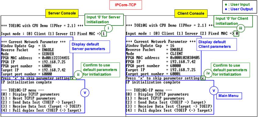
Figure 30 FPGA-Based Target Initialization (Default Parameters)
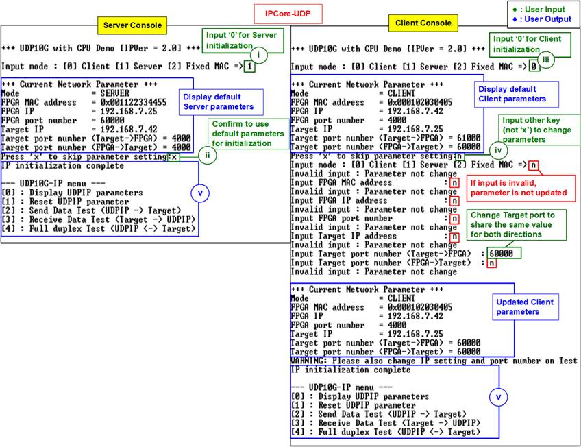
Figure 31 FPGA-Based Target
Initialization (Updated Parameters)
4 Revision History
|
Revision |
Date (D-M-Y) |
Description |
|
3.07 |
8-Jan-26 |
Support Alveo X3522 Card |
|
3.06 |
31-Jan-25 |
- Support AUBoard 15P - Support Fixed-MAC mode for UDP10G-IP |
|
3.05 |
6-Nov-24 |
Update the reference link for booting the VCK190 board |
|
3.04 |
30-Aug-24 |
- Support VCK190 board - Change “tcp_client_txrx_40G” to “tcp_client_txrx_xg” |
|
3.03 |
13-Mar-23 |
Update Figure 14 |
|
3.02 |
9-Mar-23 |
Add KCU116 and ZCU111 boards |
|
3.01 |
15-Mar-22 |
Update Figure 27, Figure 30, and Figure 31 |
|
3.00 |
21-Aug-20 |
TOE10G-IP and UDP10G-IP |
|
2.00 |
21-Jul-20 |
Remove test result on the console |
|
1.01 |
8-Mar-19 |
Support FPGA <-> FPGA test and ZCU102 |
|
1.00 |
15-Sep-17 |
Initial version release |