FPGA Setup for TOE200GADV-IP Demo
1 Overview
This document provides a guide for setting up the FPGA board and preparing the necessary test environment to run the TOE200GADV-IP demo. The reference design supports connections to up to two target devices simultaneously, allowing the user to enable one or two TOE200GADV-IP instances depending on the number of target devices in the system.
The target device can be either a PC equipped with 200G Ethernet, which offers a more flexible and fully functional testing environment, or another FPGA board that integrates the TOE200GADV-IP, enabling high-performance data transfers at the full 200G Ethernet bandwidth. This allows users to evaluate the IP core in a range of scenarios, from practical PC-based testing to high-throughput FPGA-to-FPGA communication, as illustrated in Figure 1.
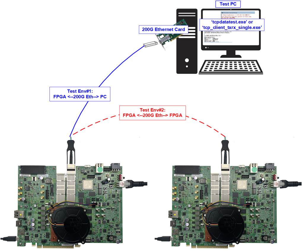
Figure 1 Test Environment for the Demo
To support PC-based target testing, Design Gateway provides two software applications: “tcpdatatest” for half-duplex data transfer, and “tcp_client_txrx_single” for full-duplex data transfer. The standard “ping” command can also be used from the PC’s command prompt to verify Ethernet connectivity with the FPGA-based host device.
When using a PC as the target device, transfer performance may be limited by the PC’s hardware resources. In contrast, FPGA-to-FPGA communication can demonstrate the full performance capabilities of the TOE200GADV-IP.
A PC running a Serial console application is required to connect to the FPGA-based host via USB for test configuration and status monitoring. This PC can also serve as the PC-based target device.
2 Test Environment Setup
The demo requires at least one FPGA-based system to act as the host, while the target system can be either PC-based system or FPGA-based system. This section outlines the hardware requirements and setup procedures for running the test.
2.1 Hardware List
To perform the demo, both host and target systems must support 200G Ethernet connectivity. Below is an example hardware list for each system type.
FPGA-Based System (Host or Target)
· FPGA development board: VPK120 or VHK158 board.
· 200G Ethernet connectivity: 200G QSFP56 AOC cable for 4-lane using PAM4.
· USB cable connecting the FPGA to the PC.
· VPK120: a micro-USB cable for FPGA programming and Serial console access
· VHK158: a USB type-C cable for FPGA programming and Serial console access
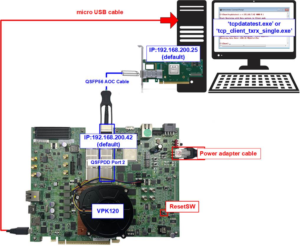
Figure 2 FPGA-Based Host/Target on VPK120

Figure 3 FPGA-Based Host/Target on VHK158
PC-Based Target System
· PC equipped with a 200 Gigabit Ethernet adapter.
· 200G Ethernet connectivity: QSFP56 AOC cable for 4-lane using PAM4
· Test applications provided by Design Gateway:
· “tcpdatatest.exe” (for half-duplex testing)
· “tcp_client_txrx_single.exe” (for full-duplex testing)
· If the same PC is used to control and configure the host FPGA, it must also have:
· AMD Vivado Design Suite
· Serial Console application (e.g., Tera Term)
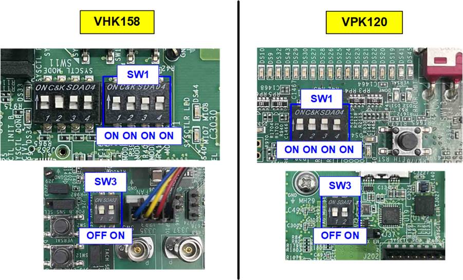
Figure 4 PC-Based Target System
Note: Below is an example configuration used to run the demo successfully:
· 200G Network Adapter: NVIDIA ConnectX-6 Dx Ethernet Adapter Card, MCX623105AC-VDAT
https://docs.nvidia.com/networking/display/connectx6dxen
· QSFP56 AOC cable
https://www.sfpcables.com/200g-qsfp56-to-qsfp56-aoc-850nm-3-20-meter-mel-3m-mel-3m
2.2 FPGA Setup
The following steps describe how to set up an FPGA board to run the TOE200GADV-IP demo.
1) Ensure the power switch is turned off before connecting the power supply cable to the FPGA board.
2) Connect the FPGA board to the target device using a QSFP56 AOC cable, as illustrated in Figure 5. The target device can be either a PC equipped with a 200G Ethernet adapter or another FPGA board.
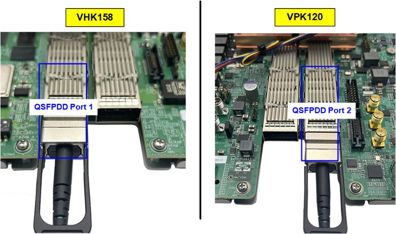
Figure 5 200G Ethernet Connection
3) Set DIP switches SW1 to “ON ON ON ON” and SW3 to “OFF ON” to JTAG boot.
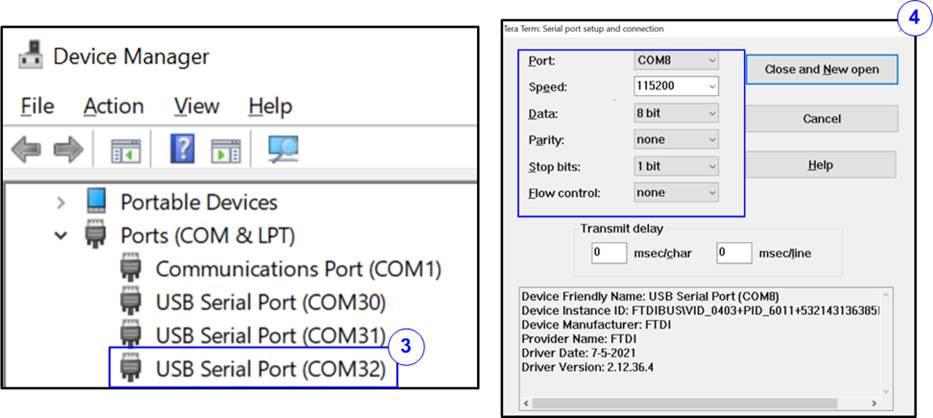
Figure 6 FPGA Board Boot Setting
4) Connect a USB cable from the FPGA board to the PC for JTAG programming and Serial console access. The PC should detect and recognize three USB Serial Ports.
· VPK120 board: Connect a micro-USB cable.
· VHK158 board: Connect a USB Type-C cable.
5) Open a Serial console and connect to the third USB Serial Port with following settings: Baud rate=115,200, Data=8-bit, Parity=None, and Stop bits=1-bit.
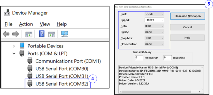
Figure 7 Serial Console for Boot-up
6) Turn on the power switch on the FPGA board.
7) Check the system-controller boot message in the Serial console to determine whether the BEAM tool is enabled. The verification and configuration procedures for the VPK120 and VHK158 boards are described below.
VPK120 Board
i) Wait for the boot message to display on the console.
· If the message “Connect to this XSDB server use host Xilinx-versal-system-controller-20221 and port 54321” is displayed (as shown in the right window of Figure 8), proceed to step (8).
· If the message from the BEAM tool is displayed (as shown in the left window of Figure 8), continue to the next step to disable the BEAM tool so that the “VPK120 – Board User Interface” application can be used for clock configuration.
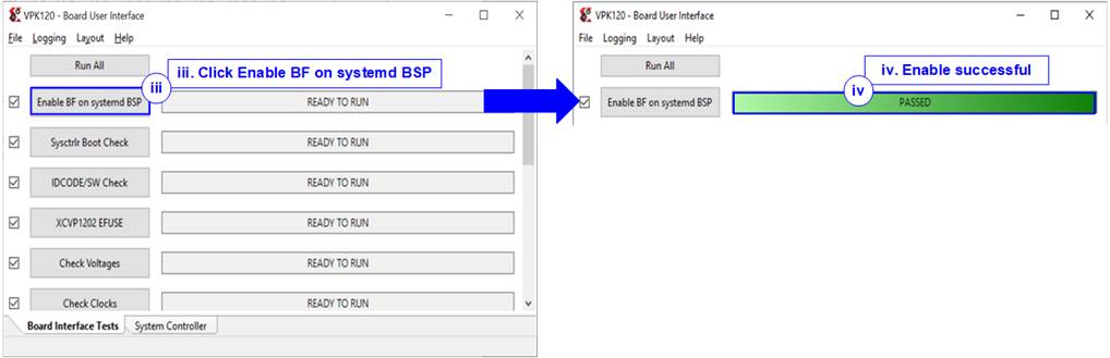
Figure 8 Boot-up Message for VPK120 Board
ii) Close the Serial console to avoid port collisions.
iii) Open the “VPK120 – Board User Interface” application and click “Enable BF on system BSP”, as shown in Figure 9.
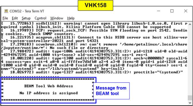
Figure 9 Enable Board Framework on VPK120
iv) Wait until the message “PASSED” is displayed in the “Enable BF on system BSP” status.
v) Power off and on the board. Re-open the Serial console and check the boot message to ensure the BEAM tool is disabled.
VHK158 Board
The Board User Interface is not available for the VHK158 board. Instead, the BEAM tool is used, and its status is displayed in the boot-up message, as shown in Figure 10.
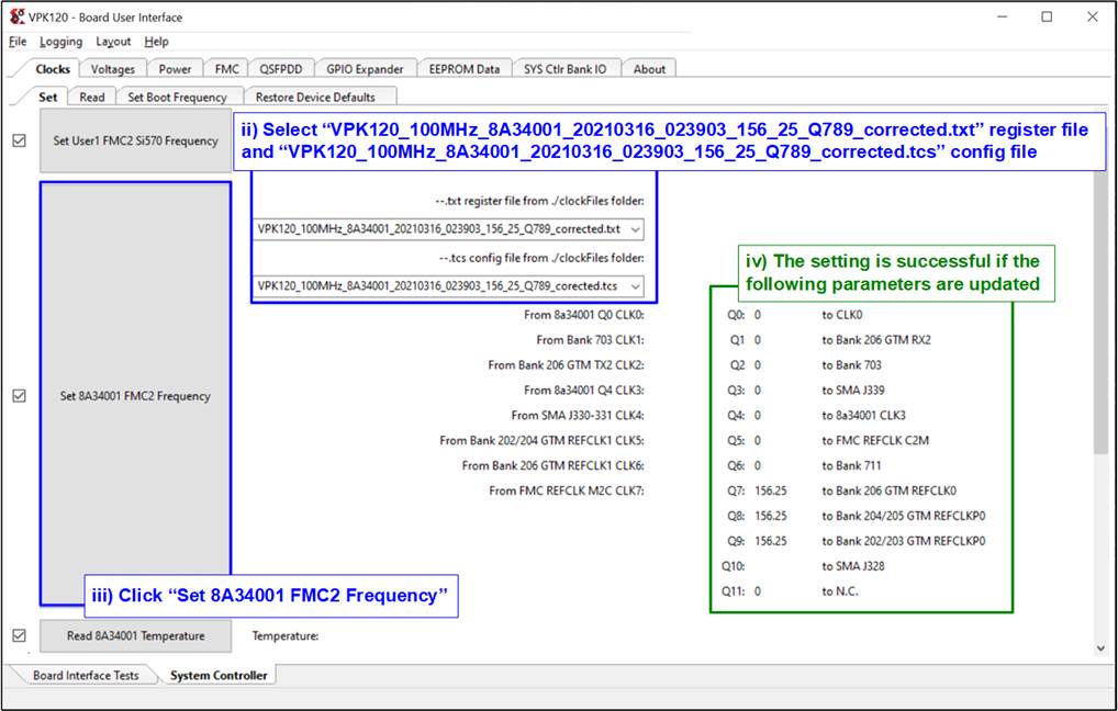
Figure 10 Boot-up Message of the BEAM Tool for VHK158
8) Configure the programmable clock for the FPGA board. Determine whether your board requires a programmable clock setup. If the board is already configured to use the desired clock frequency, you do not need to re-configure it.
VPK120 Board
i) Close the Serial console to avoid port collisions and open the “VPK120 – Board User Interface” application.
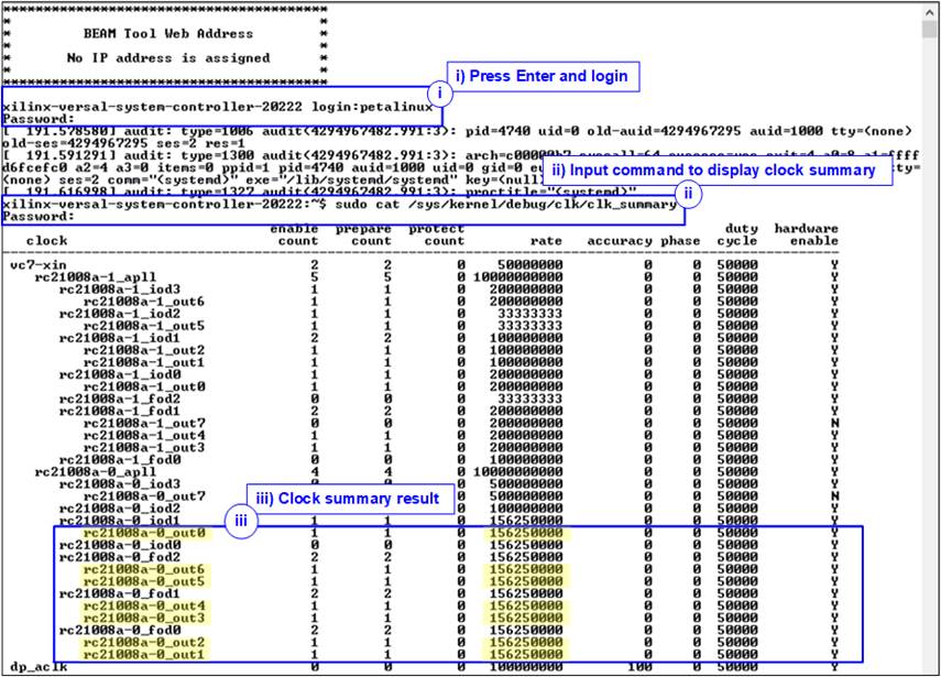
Figure 11 Reference Clock Programming for VPK120
ii) Select the register file and config file option to the profile: “VPK120_100MHz_8A34001_20210316_023903_ 156_25_Q789_corrected” to set the programmable clock to 156.25 MHz.
iii) Click “Set 8A34001 FMC2 Frequency” to program the clock configuration.
iv) Wait until the parameters displayed on the right side are updated. Ensure that the clock frequencies for Q7 – Q9 are set to 156.25.
VHK158 Board
Use the system controller to confirm the current clock frequency of the programmable clock on the board as follows:
i) Press the “ENTER” key to display login console, and then log in with the username: “petalinux”.
ii) Enter the following command:
>> sudo cat /sys/kernel/debug/clk/clk_summary
This command displays the current clock frequency on the FPGA board.
iii) Verify that the clock frequency values for “rc21008a-0_out0-6” are set to 156.25 MHz, as shown in Figure 12.
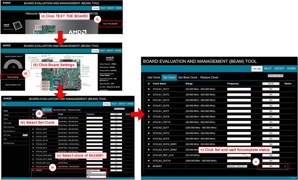
Figure 12 Current Clock Frequency of VHK158 Board
If the clock frequencies for “rc21008a-0_out0-6” are not set to 156.25 MHz, follow these steps to configure the new clock values using the BEAM tool:
i) Open the BEAM tool by following the sections: “Board and Requirements”, “Board setup and Connection”, and “Launching the GUI”, available at the following link:
ii) In the BEAM tool, click “TEST THE BOARD”, as shown Figure 13.
iii) Click “Board Settings” and select “Set Clock” from the top menu bar.
iv) Choose the clock configuration for the “8A34001” with the profile: “8A34001_2020-0318_156MHz”.
v) Click “Set” and wait for the status to display a “check mark” icon, indicating that the configuration is complete.
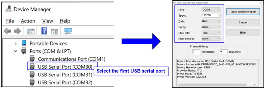
Figure 13 Programmable Clock Configuration for VHK158
9) Close the Serial console of the third USB Serial Port.
10) Download configuration file and firmware to the FPGA board. Open the Vivado Tcl shell and navigate to the download directory that contains the BAT file, PDI file, and ELF file. Run the BAT file corresponding to the FPGA board being used. Figure 14 shows the VPK120 configuration as an example.
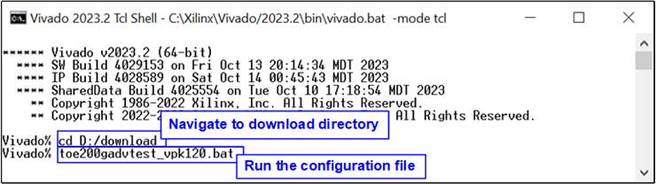
Figure 14 FPGA Configuration Using Script File on Vivado Tcl Shell
3 FPGA Initialization
This section describes the sequence for initializing the FPGA-based host and establishing communication with the target device. When an FPGA-based target is used, the target FPGA must also be initialized.
1) Launch the Serial console on the first USB Serial Port with the following settings: Baud rate=115,200, Data=8-bit, Parity=None, and Stop bits=1-bit.
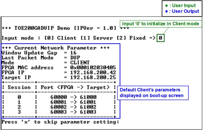
Figure 15 Serial Console Configuration
2) Once the Serial console is launched, a welcome message is displayed showing the demo name and IP Core version. The demo will wait until the Ethernet link is established. If the link is down, a status message will be displayed every 5 seconds. Once the link is up, the user will be prompted to configure local host parameters – this is the first step in the TOE200GADV-IP initialization process, as shown in Figure 16.
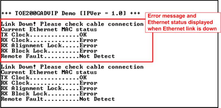
Figure 16 Message after Boot-up
To access the main menu, the user must first initialize the local host FPGA and the target device with the appropriate initialization mode. The rules for setting the initialization modes are as follow:
· If the host FPGA and the target device are on the same IP subnet, three initialization modes can be used: Server <-> Client, Fixed-MAC <-> Fixed-MAC, and Fixed-MAC <-> Client. For a PC-based target, it is recommended to configure the host FPGA in Client mode.
· If the host FPGA and the target device are on different IP subnet, only Fixed-MAC mode is supported. In this case, the Target MAC address must be set to the MAC address of the local gateway/router.
Note: Client, Server, and Fixed-MAC in this section refer to the MAC-address/ARP initialization modes, not to the TCP Client/Server role used during a TCP test.
This document presents an example setup with one host FPGA and one target FPGA. The host is configured in Client mode (to send an ARP request), and the target is configured in Server mode (to respond with an ARP reply). Once the Ethernet link is up, follow the steps below to initialize both devices.
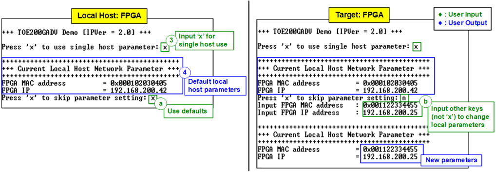
Figure 17 Setting Local Host Parameters
3) The console prompts the user to select a single-host configuration. For standard testing, input ‘x’ to use a single local-host configuration. Both TOE200GADV-IP instances on the FPGA board then share the same local network settings.
Note: Multi-host configurations are reserved for internal testing only. If this functionality is required, please contact our sales team for further assistance.
4) The console displays the default local host parameters. The user can:
· Input ‘x’ to use default settings (left window - for host system configuration), or
· Press any other key to manually edit the parameters (right window – for configuring an FPGA-based target system).
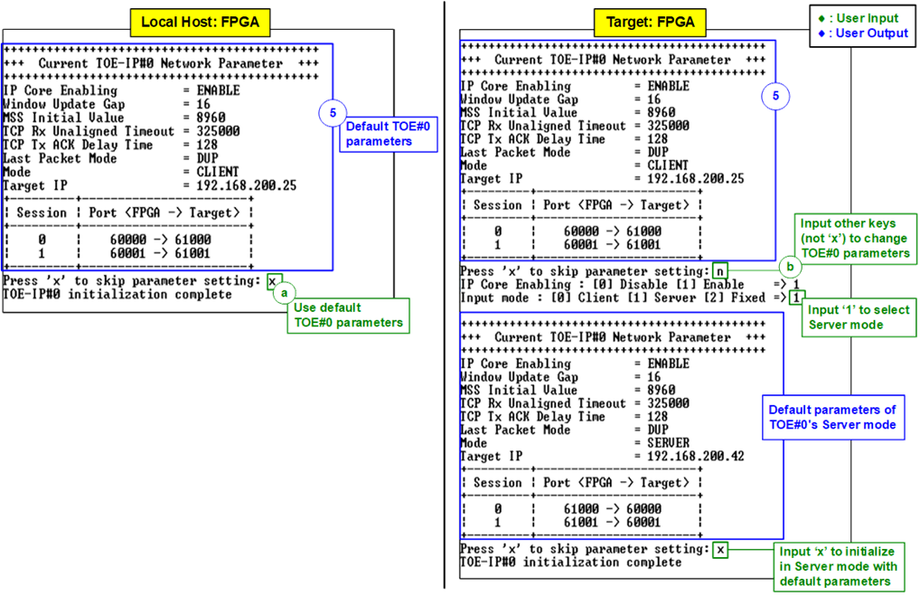
Figure 18 Setting TOE#0 Parameters
5) Parameter settings for TOE#0 (the 1st TOE200GADV-IP instance) are displayed. After setting the parameters, TOE#0 begins its initialization. The console reports “TOE#0 initialization complete” when finished.
In this example:
· On the host FPGA console (left window), input ‘x’ to initialize TOE#0 in Client mode using default parameters.
· On the target FPGA console (right window), press any key other than ‘x’ to enter parameter-setting mode. Input ‘1’ to select Server mode, and then input ‘x’ to accept the default Server-mode parameters.
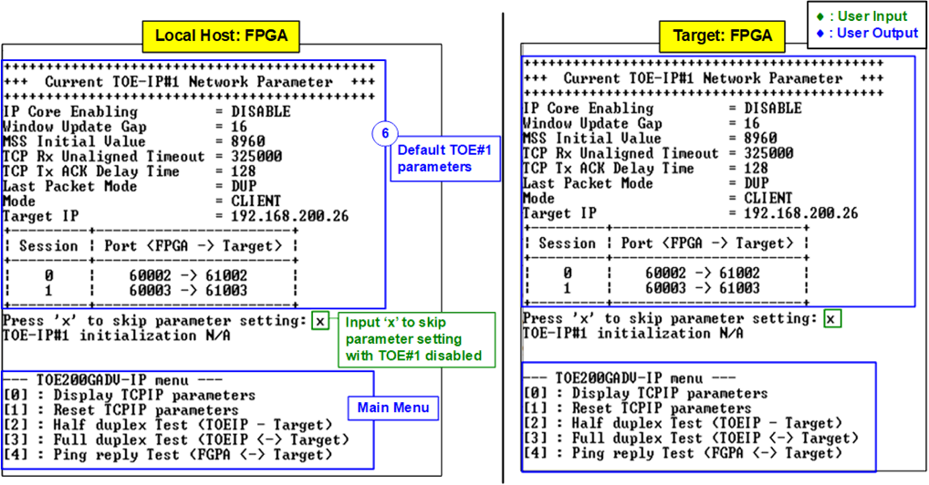
Figure 19 Setting TOE#1 Parameters
6) Parameter settings for TOE#1 (the 2nd TOE200GADV-IP instance) are then displayed. On the host FPGA console (left window), input ‘x’ to accept the default settings without modification. TOE#1 remains disabled and in reset, and the console displays “TOE#1 initialization N/A”, followed by the main test menu. Do the same on the target FPGA if TOE#1 is unused (right window).
In this example, only TOE#0 is initialized for communication between the host and target device, while TOE#1 remains disabled. To enable both TOE200GADV-IP instances and allow the host to communicate with two target devices simultaneously, refer to the “Reset TCPIP Parameters” menu in the “dg_toe200gadvip_instruction” document for detailed instructions.
4 Revision History
|
Revision |
Date (D-M-Y) |
Description |
|
2.00 |
28-Aug-26 |
Support two target devices |
|
1.00 |
4-Dec-24 |
Initial version release |