TOE25G-IP Core Data Sheet
PKL and TDL setting in Send command
Connection termination of unusual case

Core Facts |
|
|
Provided with Core |
|
|
Documentation |
Reference design manual, Demo instruction manual |
|
Design File Formats |
Encrypted File |
|
Instantiation Templates |
VHDL |
|
Reference Designs & Application Notes |
Quartus Project, See Reference Design Manual |
|
Additional Items |
Demo on Stratix10 GX board, Stratix10 MX board, and Agilex 7 F-Series development Kit |
|
Support |
|
|
Support Provided by Design Gateway Co., Ltd. |
|
Design Gateway Co.,Ltd
E-mail: ip-sales@design-gateway.com
URL: design-gateway.com
Features
· TCP/IP stack implementation
· Support IPv4 protocol
· Support one session for each TOE25G IP (Multisession can be implemented by using multiple TOE25G IPs)
· Support both Server and Client mode (Passive/Active open and close)
· Support Jumbo frame
· Transmitted packet size aligned to 128-bit, transmitted data bus size
· Total amount of received data size aligned to 128-bit, received data bus size
· Simple data interface by standard FIFO interface at 128-bit data bus
· Simple control interface by 32-bit single-port RAM interface
· 64-bit Avalon stream to interface with Ethernet MAC
· Various transmit and receive buffer sizes to optimize resource usage or performance
· Minimum user clock frequency: Ethernet MAC Clock/2 (201.416 MHz or 195.3125 MHz)
· Ethernet speed (10G or 25G) selected by the model of Ethernet MAC and PCS
· Reference design available on Stratix10 GX (H-Tile), Stratix10 MX board, and Agilex 7 F-Series development Kit
· Not support IP fragmentation feature
· Customized service for following features
· Unaligned 128-bit data transferring
· Buffer size extension by using Windows Scaling feature
· Network parameter assignment by other methods
Table 1: Example Implementation Statistics
|
Family |
Example Device |
Fmax (MHz) |
ALMs1 |
Registers1 |
Pin |
Block Memory bit2 |
Design Tools |
|
Stratix 10 GX |
1SG280HU2F50E1VG |
350 |
3,273 |
5,636 |
- |
1,179,648 |
QuartusII20.1 |
|
Agilex 7 F-Series |
AGFB014R24A2E3VR0 |
350 |
3,231 |
5,792 |
- |
1,179,648 |
QuartusII20.4 |
Notes:
1) Actual logic resource dependent on percentage of unrelated logic
2) Block memory resources are based on 64KB Tx data buffer, 16KB Tx packet buffer, and 64KB Rx data buffer. The minimum buffer sizes for jumbo frame are 8KB Tx data buffer, 8KB Tx packet buffer, and 16KB Rx data buffer.
Applications
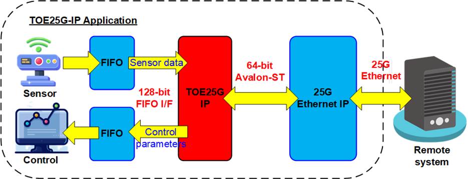
Figure 1: TOE25G IP Application
The 25G Ethernet is a communication channel for transferring data with remote controlling system. When combined with the TCP/IP protocol, this system can ensure reliable data transfer at high-speed rate via 25G Ethernet network. TOE25G IP is an integrated IP that enables data transfer via 25G Ethernet without requiring the use of CPU or external memory. It is suitable for applications that require high-speed data transfer, such as video data streaming and sensor monitoring system using FPGA solutions.
Figure 1 shows an example application of a sensor monitoring system, where data from the sensor is stored in a FIFO and forwarded to a remote system via 25G Ethernet using the TOE25G IP. The TOE25G IP supports full-duplex transfer in the same TCP session, allowing the Remote system to set parameters for real-time controlling the sensor monitoring system via 25G Ethernet while receiving the data from TOE25G IP via 25G Ethernet network.
General Description
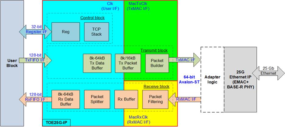
Figure 2: TOE25G IP Block Diagram
The TOE25G IP core is a hardwired logic implementation of the TCP/IP stack that connects with 25G Ethernet IP to form the lower layer hardware. The user interface of TOE25G IP consists of two interfaces, i.e., the Register interface for control signals and the FIFO interface for data signals.
To access up to 32 registers, the Register interface uses a 5-bit address. The registers store network parameters, commands, and system parameters. Each TOE25G IP can operate one session to communicate with a single target device. Network parameters must be set before de-asserting the reset signal to execute IP initialization. After the reset operation and parameter initialization are complete, the IP is ready to transfer data with the target device. Network parameters cannot be changed without a reset process and the TOE25G IP has three initialization modes for obtaining the MAC address of the target device. Further details of each mode can be found in the IP Initialization topic.
To transfer data with the user, a 128-bit FIFO interface is used. However, there is no byte enable in the FIFO interface, so the transmitted data from the user must be aligned to 128-bit. The packet length and the total amount of transmitted data must also be aligned to 128-bit. On the other hand, the received data on the Rx FIFO I/F can be read when at least one 128-bit data is available in the Rx data buffer. If the total amount of received data is not aligned to 128-bit, the user cannot read the last data and must wait until the next data is received to fill the remaining byte of 128-bit data for reading the Rx data buffer.
The TOE25G IP has asynchronous buffers that enable the user interface to run on an independent clock that has a lower frequency than the Ethernet MAC clock frequency. However, it is recommended to use half of Ethernet MAC clock frequency or more as the user clock frequency. Using a too slow frequency clock reduce transfer performance.
In accordance with TCP/IP standard, connection establishment is the first step before transferring data. TOE25G IP supports both active open (the IP opens the port) and passive open (the target device opens the port) modes. After a successful connection, data can be transferred via the new connection. To send TCP payload data, the user must set the total transfer size, packet size, and send command to the IP. The TCP payload data is transferred via the TxFIFO interface. Conversely, when the TCP packet is received from the target, the TCP payload data is extracted and stored to the Rx data buffer. The user logic monitors FIFO status to detect the amount of received data and then asserts read enable to read the data via the RxFIFO interface. When there is no more data to transfer, the connection can be terminated by closing the port. TOE25G IP supports both active close (the IP closes the port) and passive close (the target device closes the port) modes.
To meet the user system requirement, which may be sensitive on the memory resource or the performance, the buffer size inside the IP can be assigned by the user. There are three buffers whose sizes can be adjusted - Tx data buffer, Tx packet buffer, and Rx data buffer. Using a bigger buffer size may increase the transfer performance in each direction. Further details about the hardware inside the IP are described in the next topic.
Functional Description
As shown in Figure 2, TOE25G IP can be divided into three blocks - control block, transmit block, and receive block. The details of each block are described as follows.
Control Block
· Reg
All parameters of the IP are set via register interface that consists of 5-bit address signals and 32-bit data signals. The timing diagram of the Register interface is similar to a single-port RAM interface, as shown in Figure 6. The write and read address are the same signal. Table 2 provides a description of each register.
Table 2: Register map Definition
|
RegAddr [4:0] |
Reg Name |
Dir |
Bit |
Description |
|
00000b |
RST |
Wr /Rd |
[0] |
Reset IP. 0b: No reset, 1b: Reset. Default value is 1b. Once the network parameters have been assigned, the user can execute system initialization by setting this register to 1b and then 0b. This action loads the parameters into the IP and executes the system initialization. If the user needs to update certain parameters, this process must be repeated by setting this register to 1b and then 0b again. The RST register controls the following network parameters: SML, SMH, DML, DMH, DIP, SIP, DPN, SPN, and SRV. |
|
00001b |
CMD |
Wr |
[1:0] |
User command. 00b: Send data, 10b: Open connection (active), 11b: Close connection (active), 01b: Undefined. The command operation begins after the user sets CMD register. In order to start a new operation by setting this register, the system must first be in Idle state. To confirm that the system is not busy, the user should read bit[0] of CMD register or RegDataA1 output, which should be equal to 0b.. |
|
Rd |
[0] |
System busy flag. 0b: Idle, 1b: IP is busy. |
||
|
[3:1] |
Current IP status. 000b: Send data, 001b: Idle, 010b: Active open, 011b: Active close, 100b: Receive data, 101b: Initialization, 110b: Passive open, 111b: Passive close. |
|||
|
00010b |
SML |
Wr /Rd |
[31:0] |
Define 32-bit lower MAC address (bit [31:0]) for this IP. To update this value, the IP must be reset by RST register. |
|
00011b |
SMH |
Wr /Rd |
[15:0] |
Define 16-bit upper MAC address (bit [47:32]) for this IP. To update this value, the IP must be reset by RST register. |
|
00100b |
DIP |
Wr /Rd |
[31:0] |
Define 32-bit target IP address. To update this value, the IP must be reset by RST register. |
|
00101b |
SIP |
Wr /Rd |
[31:0] |
Define 32-bit IP address for this IP. To update this value, the IP must be reset by RST register. |
|
00110b |
DPN |
Wr /Rd |
[15:0] |
Define 16-bit target port number. Unused when the port is opened in passive mode. To update this value, the IP must be reset by RST register. |
|
00111b |
SPN |
Wr /Rd |
[15:0] |
Define 16-bit port number for this IP. To update this value, the IP must be reset by RST register. |
|
01000b |
TDL |
Wr |
[31:0] [31:0] |
Total Tx data length in byte unit. The value must be aligned to 16-byte because bit[3:0] are not used. Valid range is 16-0xFFFFFFF0. The user must first set this register before setting CMD register = Send data (00b). When the IP executes the �Send data� command and asserts Busy to 1b, the system will read this register, allowing the user to subsequently set the TDL register for the next command. If the same TDL is used in the subsequent command, the user is not required to set TDL again. |
|
Rd |
Remaining transfer length in byte unit which does not transmit. |
|
RegAddr [4:0] |
Reg Name |
Dir |
Bit |
Description |
|
01001b |
TMO |
Wr |
[31:0]
|
Define timeout value for awaiting the return of an Rx packet from the target. The counter runs based on the Clk signal provided by the user, with the timer unit being equal to 1/Clk. If the packet is not received within the specified time, TimerInt will be asserted to 1b. For further information of TimerInt, please refer to the Read value of TMO[7:0] register. It is recommended to set the TMO to a value greater than 0x6000. |
|
Rd |
The details of timeout interrupt are shown in TMO[7:0]. Other bits are read for IP monitoring. [0]-Timeout from not receiving ARP reply packet After timeout, the IP resends ARP request until ARP reply is received. [1]-Timeout from not receiving SYN and ACK flag during active open operation After timeout, the IP resends SYN packet for 16 times and then sends FIN packet to close connection. [2]-Timeout from not receiving ACK flag during passive open operation After timeout, the IP resends SYN/ACK packet for 16 times and then sends FIN packet to close connection. [3]-Timeout from not receiving FIN and ACK flag during active close operation After the 1st timeout, the IP sends RST packet to close connection. [4]-Timeout from not receiving ACK flag during passive close operation After timeout, the IP resends FIN/ACK packet for 16 times and then sends RST packet to close connection. [5]-Timeout from not receiving ACK flag during data transmit operation After timeout, the IP resends the previous data packet. [6]-Timeout from Rx packet lost, Rx data FIFO full, or wrong sequence number The IP generates duplicate ACK to request data retransmission. [7]-Timeout from too small receive window size when running Send data command and setting PSH[2] to 1b. After timeout, the IP retransmits data packet, similar to TMO[5] recovery process. [21]-Lost flag when the sequence number of the received ACK packet is skipped. As a result, TimerInt is asserted and TMO[6] is equal to 1b. [22]-FIN flag is detected during sending operation. [23]-Rx packet is ignored due to Rx data buffer full (fatal error). [27]-Rx packet lost detected [30]-RST flag is detected in Rx packet [31],[29:28],[26:24]-Internal test status |
|||
|
01010b |
PKL |
Wr /Rd |
[15:0] |
TCP data length of each Tx packet in byte unit. The value must be aligned to 16-byte because bit[3:0] are not used. Valid from 16-8960. Default value is 1456 byte, which is the maximum size of non-jumbo frame and aligned to 16-byte. During running Send data command (Busy=1b), the user must not set this register. Similar to TDL register, the user does not need to set PKL register again if the next command uses the same packet length. |
|
01011b |
PSH |
Wr /Rd |
[2:0] |
Sending mode when running Send data command. [0]-Disable to retransmit packet. 0b: Generate the duplicate data packet for the last data packet in Send data command when TDL value is not equal to N times of PKL value to accelerate ACK packet (default). 1b: Disable the duplicate data packet. [1]-PSH flag value in TCP header for all transmitted packet. 0b: PSH flag = 0b (default). 1b: PSH flag = 1b. |
RegAddr [4:0] |
Reg Name |
Dir |
Bit |
Description |
|
01011b |
PSH |
Wr /Rd |
[2:0] |
[2]-Enable to retransmit data packet when Send data command is paused until timeout, caused by the receive window size being smaller than the packet size. This flag is designed to resolve the system hang problem resulting from lost window update packet. Activating data retransmission prompts the target device to regenerate the lost window update packet. All following conditions must be met to initiate data retransmission. (1) PSH[2] is set to 1b. (2) The current command is �Send data� and all data are not completely sent. (3) The receive window size is smaller than the packet size. (4) Timer set by TMO register is overflowed. 0b: Disable the feature (default), 1b: Enable the feature. |
|
01100b |
WIN |
Wr /Rd |
[5:0] |
Threshold value in 1Kbyte unit to initiate window update packet transmission. Default value is 0 (Not enable window update transmission). The IP sends the window update packet when the free space in the Rx data buffer increases by an amount greater than the threshold value from the value in the most recently transmitted packet. For example, if the user sets WIN=000001b (1 Kbyte) and the window size of the most recently transmitted packet is 2 Kbyte, when the user reads 1 Kbyte data from the IP and the free space in the Rx data buffer is updated from 2 Kbyte to be 3 Kbyte, the IP detects that the increased window size is greater than the threshold value of 1 Kbyte (3 KB � 2 KB). As a result, the IP sends the window update packet to update the receive buffer size. |
|
01101b |
ETL |
Wr |
[31:0] |
Extended total Tx data length in byte unit. The value must be aligned to 16-byte and bit[3:0] are not used. The user can set this register during the Send data command operation (Busy=1b) to extend the total Tx data length. This allows for continuous data transmission without having to resend a new command to the IP. However, there are some important considerations to use this feature: 1) The ETL register must be programmed when the read value of TDL is not less than 128 Kbytes to ensure that Busy is not de-asserted to 0b before setting the ETL register. 2) The set value of ETL must be less than the maximum value of TDL (0xFFFFFFF0) minus the read value of TDL, to avoid overflow value. For example, the user sets TDL to 3.5 GB and then sets CMD register to Send data. After the IP completes 2 GB of data (remaining size = 1.5 GB), the user sets the ETL register to 1.5 GB. The total transmit length is equal to 5 GB (3.5 GB of TDL + 1.5 GB of ETL). |
|
01110b |
SRV |
Wr /Rd |
[1:0] |
00b: Client mode (default). When the RST register changes from 1b to 0b, the IP sends an ARP request to obtain the Target MAC address from the ARP reply returned by the target device. The IP busy signal is de-asserted to 0b after receiving the ARP reply. 01b: Server mode. When RST register changes from 1b to 0b, the IP waits for an ARP request from the target to obtain Target MAC address. After receiving the ARP request, the IP generates an ARP reply and then de-asserts the IP busy signal to 0b. 1Xb: Fixed MAC Mode. When the RST register changes from 1b to 0b, the IP updates all internal parameters and then de-asserts IP busy to 0b. Target MAC address is loaded through the DML/DMH register. Note: In Server mode, when RST register changes from 1b to 0b, the target device must resend an ARP request for the TOE25G IP to complete the IP initialization process. |
|
01111b |
VER |
Rd |
[31:0] |
IP version |
|
10000b |
DML |
Wr /Rd |
[31:0] |
Define 32-bit lower target MAC address (bit [31:0]) for this IP when SRV[1]=1b (Fixed MAC). To update this value, the IP must be reset by RST register. |
|
10001b
|
DMH |
Wr /Rd |
[15:0] |
Define 16-bit upper traget MAC address (bit [47:32]) for this IP when SRV[1]=1b (Fixed MAC). To update this value, the IP must be reset by RST register. |
· TCP Stack
To transfer data between the TOE25G IP and the target device, three processes are involved: port opening, data transfer, and port closing. The IP supports active open or close by sending SYN or FIN packets when the user sets the CMD register to 10b (port opening) or 11b (port closing). Alternatively, the port can be opened or closed by the target device (passive mode) when the TCP Stack receives SYN or FIN packet. While the port is being opened or closed, the Busy flag is asserted to 1b. Once all packets are transferred, Busy is de-asserted to 0b. The ConnOn signal can be applied to check if the port status is completely opened or closed. The data can be transferred when ConnOn is asserted to 1b (indicating that the port is completely opened).
To send the data, user data is stored in the Tx data and Tx packet buffers. Packet Builder uses the network parameters set by the user to build TCP header, and then the data of Tx data buffer is appended to the TCP packet. The Transmit block then sends the TCP packet to the target device via Ethernet MAC. If the target device receives the data correctly, an ACK packet is returned to Receive block. The TCP Stack monitors the status of the Transmit and Receive blocks to confirm that the data has been sent successfully. If the data is lost, the TCP Stack pauses the current data transmission and initiates the data retransmission process in Transmit block.
When the Receive block receives data, TCP Stack checks the order of the received data. If the data is in the correct order, a normal ACK packet is generated by the Transmit block. Otherwise, the TCP Stack starts the lost data recovery process by instructing the Transmit block to generate duplicate ACKs to the target device.
Table 3: TxBuf/TxPac/RxBufBitWidth Parameter description
|
Value of BitWidth |
Buffer Size |
TxBufBitWidth |
TxPacBitWidth |
RxBufBitWidth |
|
9 |
8kByte |
Valid |
Valid |
Valid |
|
10 |
16kByte |
Valid |
Valid |
Valid |
|
11 |
32kByte |
Valid |
No |
Valid |
|
12 |
64kByte |
Valid |
No |
Valid |
Transmit Block
Transmit block contains two buffers - Tx data buffer and Tx packet buffer � whose sizes can be adjusted through parameter assignment. A larger buffer size may improve transmit performance. However, the minimum size of these buffer is limited by the transmit packet size, set by PKL register. Data from the Tx data buffer is split into packets based on the packet size and stored in the Tx packet buffer. TCP header is constructed using the network parameters from the Reg module and then combined with the TCP data from the Tx packet buffer to form a complete TCP packet. The data in the Tx data buffer is flushed after the target device sends an ACK packet. Once the Send data command is completed, the user can initiate the next command.
· Tx Data Buffer
The size of this buffer is determined by the �TxBufBitWidth� parameter of the IP, with valid value ranging from 9-12 (8KB to 64 KB), which corresponds to the address size of a 128-bit buffer as shown in Table 3. The buffer size should be at least twice the size of the Tx Packet Size set in the PKL register. This buffer stores data from the user to prepare the transmit packet sent to the target device. Data is removed from the buffer when the target device confirms that the data has been completely received. When the buffer size is large enough, the IP can send multiple data packets to the target device without waiting for an ACK packet to clear the buffer. The user can continuously store new data in the Tx data buffer without waiting for long periods. This results in the best transmit performance on a 25G Ethernet connection. However, if there is significant latency time due to the carrier, networking interface, or target system, all the data in the Tx data buffer may be transferred before an ACK packet is returned to flush the buffer. In such cases, the user must pause filling the buffer with new data, resulting in reduced transmit performance.
If the total user data is greater than the value of the TDL register, the buffer will still have remaining data after completing the current Send command. This data can be applied for the next Send command. All data in the buffer is flushed when the connection is closed or the IP is reset.
Note: The IP cannot send the packet if the data stored in the buffer is less than transmit size. The IP must wait until the data from user is sufficient to create one packet.
· Tx Packet Buffer
The size of the buffer size is determined by the �TxPacBitWidth� parameter of the IP. Its valid range is 9-10 (8KB and 16 KB), and the details of the parameter are shown in Table 3. To store at least one transmit packet, the buffer size must be larger than the Tx packet size set by the PKL register. Note that the maximum value of the PKL register is equal to the Tx Packet Buffer size (in bytes) minus 48.
· Packet Builder
The TCP packet is comprised of a header and data. The Packet builder first receives network parameters from the Reg module and uses them to construct the TCP header. The TCP and IP checksum are also calculated for the header. Once the header is fully constructed, it is combined with the data from the Tx packet buffer and then transmitted to the EMAC.
Receive Block
The Receive block contains the Rx data buffer, which stores the data received from the target device. The received data is stored in the buffer when the header in the packet matches the expected value, set by the network parameters inside the Reg module, and when the IP and TCP checksum are correct. If any of these conditions are not met, the received packet is rejected. Increasing the size of the Rx data buffer may improve the receive performance. Additionally, the TOE25G IP can reorder packets if only one packet is out of order. For example, if the packet order is #1, #3, #2 and #4 (where packet #2 is interchanged with packet#3), the TOE25G IP can fix the order. However, if more than one packet is out of order, such as in the case of packet#1, #3, #4, and #2 (where packet #3 and #4 are received before packet#2), the TOE25G IP is unable to reorder the packets. In this scenario, the data needs to be retransmitted, and duplicate ACK packets must be generated.
· Rx Buffer
This is temporary buffer that is used to hold incoming packets from EMAC in cases where the previous packet has not yet been completely processed.
· Packet Filtering
This module is responsible for verifying the header of the Rx packet to determine its validity. The packet will be valid if all following conditions are met.
(1) The network parameters must match the values set in the Reg module, such as the MAC address, IP address, and Port number.
(2) The packet must either be an ARP packet or a TCP/IPv4 packet without a data fragment flag.
(3) The IP header length and TCP header length must be valid, with the IP length being equal to 20 bytes and the TCP header length being between 20 and 60 bytes.
(4) Both the IP checksum and TCP checksum must be correct.
(5) The data pointer, as decoded by the sequence number, must be within a valid range.
(6) The acknowledge number must be within a valid range.
· Packet Splitter
The purpose of this module is to extract TCP payload data from incoming packets and store it in the Rx data buffer, after removing the packet header.
· Rx Data Buffer
The size of the Rx data buffer is determined by the �RxBufBitWidth� parameter of the IP and can range from 9 � 12 (8KB to 64 KB). The size of the Rx data buffer is also applied as the window size of the transmit packet. When the Rx data buffer is sufficiently large, the target device can send multiple data packets to the TOE25G IP without having to wait for an ACK packet, which may be delayed by the networking system. Consequently, a larger Rx data buffer can improve the receive performance.
The data is stored in the buffer until it is read by the user. If the user does not read the data from the buffer for long time, the buffer becomes full, and the target device can no longer send data to the IP, resulting in reduced performance. To achieve optimal received performance, it is recommended that the user logic reads the data from the IP as soon as it is available. By doing so, the Rx data buffer will not become full, and the receive performance will not be affected by the full window size.
User Block
The core engine of the user module can be designed by state machine to set the command and the parameters through the Register interface. Additionally, the status can be monitored to ensure that the operation has been completed without any errors. The data path can also be connected to the FIFO for sending or receiving data with the IP.
25G Ethernet IP
The 25G Ethernet IP consists of Ethernet MAC and PCS/PMA hardware components. The specific names of the IPs depend on the FPGA models. In this section, we will explore two IP components available in the IP catalog in Quartus tools. The interface of 25G Ethernet IP is a 64-bit Avalon stream, similar to the EMAC interface of the TOE25G IP.
25G Ethernet Intel FPGA IP
This IP core utilizes soft IP to implement the Ethernet MAC and PHY features. It is compatible with Stratix 10 GX and Stratix 10 MX devices. The user interface for transmitting and receiving packets operates in different clock domains, namely MacTxClk and MacRxClk. However, both clock signals share the same frequency of 390.625 MHz. For more detailed information, please refer to the Intel website at the following link.
E-tile Hard IP
The E-tile Hard IP serves as the hard IP implementation for the Ethernet MAC and PHY. It is available in Agilex 7 F-Series devices. The clock interface used for transmitting and receiving packets with the E-tile hard IP is the same, and its frequency is set at 402.832 MHz. To connect the E-tile Hard IP to the TOE25G IP, an adapter logic with a small FIFO is required. Additional information can be found on the Intel website at the following link.
Core I/O Signals
Descriptions of all parameters and I/O signals are provided in Table 4 - Table 6. The EMAC interface is 64-bit Avalon stream standard.
Table 4: Core Parameters
|
Name |
Value |
Description |
|
TxBufBitWidth |
9-12 |
Setting Tx data buffer size. The value is referred to address bus size of this buffer. |
|
TxPacBitWidth |
9-10 |
Setting Tx packet buffer size. The value is referred to address bus size of this buffer. |
|
RxBufBitWidth |
9-12 |
Setting Rx data buffer size. The value is referred to address bus size of this buffer. |
Table 5: User I/O Signals (Synchronous to Clk)
|
Signal |
Dir |
Description |
|
Common Interface Signal |
||
|
RstB |
In |
Reset IP core. Active Low. |
|
Clk |
In |
User clock. The clock frequency must be equal to or greater than half of the MacClk frequency (195.3125 MHz for 25G Ethernet on Stratix10 or 201.416 MHz for 25G Ethernet on Agilex 7). |
|
User Interface |
||
|
RegAddr[4:0] |
In |
Register address bus. Valid when RegWrEn=1b in Write process. |
|
RegWrData[31:0] |
In |
Register write data bus. Valid when RegWrEn=1b. |
|
RegWrEn |
In |
Register write enable. Valid at the same clock as RegAddr and RegWrData. |
|
RegRdData[31:0] |
Out |
Register read data bus. Available the next clock after RegAddr is valid. |
|
ConnOn |
Out |
Connection Status. 1b: connection is opened, 0b: connection is closed. |
|
TimerInt |
Out |
Timer interrupt. Asserted to high for 1 clock cycle when timeout is detected. More details of Interrupt status could be checked from TMO[7:0] register. |
|
RegDataA1[31:0] |
Out |
32-bit read value of CMD register (RegAddr=00001b). Bit[0] is TOE25G IP busy flag. |
|
RegDataA8[31:0] |
Out |
32-bit read value of TDL register (RegAddr=01000b) |
|
RegDataA9[31:0] |
Out |
32-bit read value of TMO register (RegAddr=01001b) |
|
Tx Data Buffer Interface |
||
|
TCPTxFfFlush |
Out |
Tx data buffer within the IP is reset. Asserted to 1b when the connection is closed or the IP is reset. |
|
TCPTxFfFull |
Out |
Asserted to 1b when Tx data buffer is full. User needs to stop writing data within 4 clock cycles after this flag is asserted to 1b. |
|
TCPTxFfWrCnt[11:0] |
Out |
Data counter in 128-bit unit of Tx data buffer to show the amount of data in Tx data buffer. |
|
TCPTxFfWrEn |
In |
Write enable to Tx data buffer. Asserted to 1b to write data to Tx data buffer. |
|
TCPTxFfWrData[127:0] |
In |
Write data to Tx data buffer. Valid when TCPTxFfWrEn=1b. |
|
Rx Data Buffer Interface |
||
|
TCPRxFfFlush |
Out |
Rx data buffer within the IP is reset. Asserted to 1b when the connection is opened. |
|
TCPRxFfRdCnt[11:0] |
Out |
Data counter of Rx data buffer to show the amount of received data in 128-bit unit. |
|
TCPRxFfLastRdCnt[3:0] |
Out |
Remaining byte of the last data in Rx data buffer when total amount of received data in the buffer is not aligned to 16-byte unit. User cannot read the data until all 16-byte data is received. |
|
TCPRxFfRdEmpty |
Out |
Asserted to 1b when Rx data buffer is empty. User needs to stop reading data immediately when this signal is asserted to 1b. |
|
TCPRxFfRdEn |
In |
Asserted to 1b to read data from Rx data buffer. |
|
TCPRxFfRdData[127:0] |
Out |
Data output from Rx data buffer. Valid in the next clock cycle after TCPRxFfRdEn is asserted to 1b. |
Table 6: EMAC I/O Signals
|
Signal |
Dir |
Description |
|
Tx MAC Interface (Synchronous to MacTxClk) |
||
|
MacTxClk |
In |
Clock from EMAC for synchronous with Tx MAC interface. 390.625 or 402.832 MHz for 25G Ethernet. |
|
MacTxData[63:0] |
Out |
Transmitted data. Valid when MacTxValid=1b. |
|
MacTxEmpty[2:0] |
Out |
Specify the number of bytes which are unused of the final word in the frame. |
|
MacTxValid |
Out |
Valid signal of transmitted data. |
|
MacTxSOP |
Out |
Control signal to indicate the first word in the frame. Valid when MacTxValid=1b. |
|
MacTxEOP |
Out |
Control signal to indicate the final word in the frame. Valid when MacTxValid=1b. |
|
MacTxReady |
In |
Handshaking signal. Asserted to 1b when MacTxData has been accepted. This signal must not be de-asserted to 0b when a packet is transmitting. |
|
Rx MAC Interface (Synchronous to MacRxClk) |
||
|
MacRxClk |
In |
Clock from EMAC for synchronous with Rx MAC interface. 390.625 or 402.832 MHz for 25G Ethernet. |
|
MacRxData[63:0] |
In |
Received data. Valid when MacRxValid=1b. |
|
MacRxValid |
In |
Valid signal of received data. MacRxValid must be asserted to 1b continuously for transferring a packet. |
|
MacRxEOP |
In |
Control signal to indicate the final word in the frame. Valid when MacRxValid=1b. |
|
MacRxError |
In |
Control signal asserted at the end of received frame (MacRxValid=1b and MacRxEOP=1b) to indicate that the frame has CRC error. 1b: error packet, 0b: normal packet. For Intel Ethernet IP, connect with rx_error[1] signal. |
|
MacRxReady |
Out |
Handshaking signal. Asserted to 1b when MacRxData has been accepted. MacRxReady is de-asserted to 0b for 2 clock cycles to be the gap size between each receive packet. |
Timing Diagram
IP Initialization
After the RST register value is changed from 1b to 0b, the initialization of TOE25G IP is initiated. Three modes can be executed, Client mode (SRV=00b), Server mode (SRV=01b), and Fixed MAC mode (SRV[1]=1b). The information on each mode is presented in the timing diagram below.
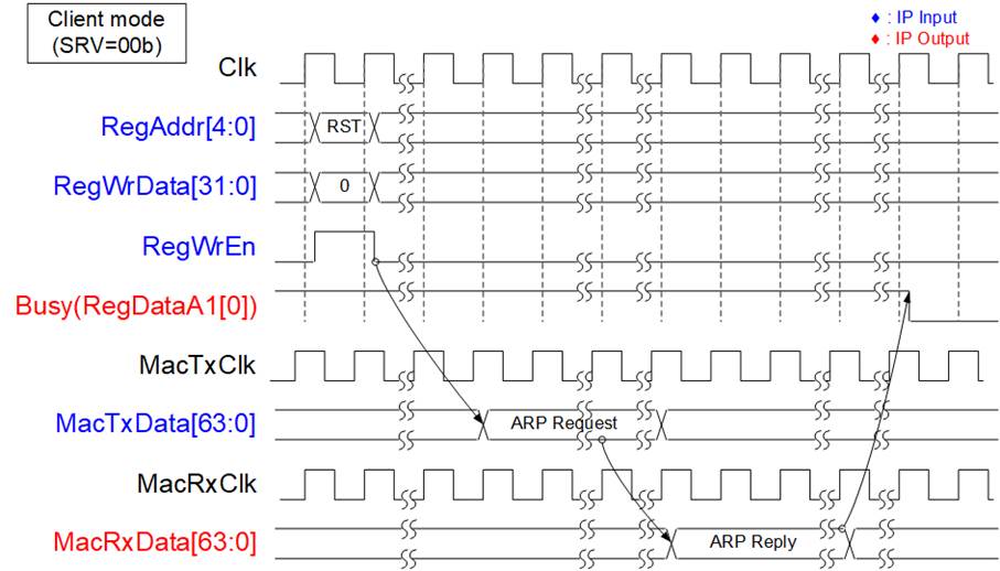
Figure 3: IP Initialization in Client mode
As shown in Figure 3, in Client mode, the TOE25G IP sends an ARP request packet and waits for an ARP reply packet returned from the target device. Target MAC address is extracted from ARP reply packet. Upon completion, the Busy signal (bit0 of RegDataA1) is de-asserted to 0b.
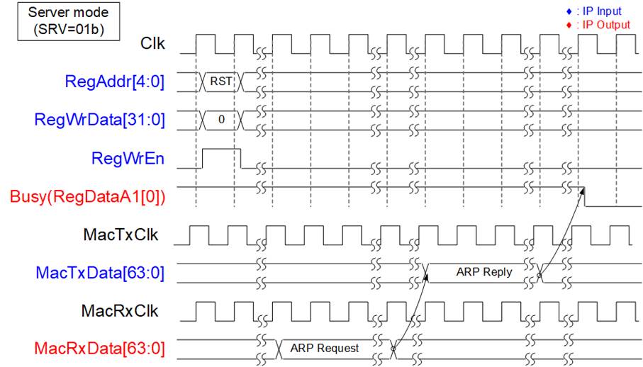
Figure 4: IP Initialization in Server mode
As shown in Figure 4, after reset process in Server mode is completed, the TOE25G IP waits for an ARP request packet from the target device. Upon receipt, the TOE25G IP generates an ARP reply packet. The Target MAC address is extracted from ARP request packet. Once the ARP reply packet has been transmitted, the Busy signal is de-asserted to 0b.
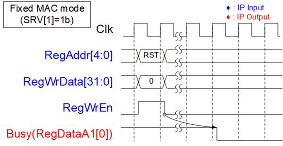
Figure 5: IP Initialization in Fixed mode
As shown in Figure 5, after reset process in Fixed MAC mode is completed, the TOE25G IP updates all parameters from the registers. The Target MAC address is loaded from DML and DMH register. Once this process is finished, the Busy signal is de-asserted to 0b.
Register Interface
The Register interface is responsible for setting and monitoring all control signals and network parameters during operation. The timing diagram of the interface is similar to that of Single-port RAM, which shares the address bus for write and read access, and has a read latency time of one clock cycle. A Register map of this interface is provided in Table 2.
As shown in Figure 6, to write to the register, the user sets RegWrEn to 1b with the valid values for RegAddr and RegWrData. Before setting RegWrEn to 1b, please confirm that RstB is de-asserted to 1b for at least 4 clock cycles. To read from the register, the user only sets RegAddr, and RegRdData becomes valid in the next clock cycle.
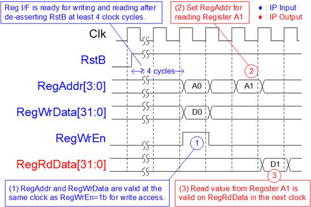
Figure 6: Register interface timing diagram
As shown in Figure 7, before setting the CMD register to initiate a new command operation, the Busy flag must be equal to 0b to confirm that IP is in Idle status. After setting the CMD register, the Busy flag is asserted to 1b and de-asserted to 0b when the command is completed.
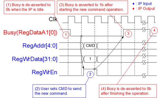
Figure 7: CMD register timing diagram
Tx FIFO Interface
Tx FIFO interface provides two control signals for the flow control, the full flag (TCPTxFfFull) and the write data counter (TCPTxFfWrCnt). TCPTxFfWrCnt is updated two clock cycles after asserting TCPTxFfWrEn. TCPTxFfFull serves as an indicator of when the internal buffer is almost full and is asserted before it reaches its capacity. It is recommended to pause sending data within four clock cycles after TCPTxFfFull is asserted. Figure 8 shows an example timing diagram for the Tx FIFO interface.
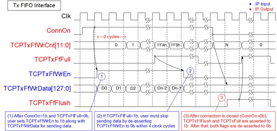
Figure 8: Tx FIFO interface timing diagram
(1) Before asserting TCPTxFfWrEn to 1b to write the data to TOE25G IP, the full flag (TCPTxFfFull) must not be asserted to 1b and ConnOn must be equal to 1b. To write the data, assert TCPTxFfWrEn to 1b along with TCPTxFfWrData.
(2) If TCPTxFfFull is asserted to 1b, TCPTxFfWrEn must be de-asserted to 0b within four clock cycles to pause sending data.
(3) When there is no more data for transferring, the connection may be terminated by active or passive mode. After the port is closed, the following situations are found.
a) ConnOn changes from 1b to 0b.
b) TCPTxFfFlush is asserted to 1b to flush all data inside TxFIFO for a while and then de-asserted to 0b.
c) TCPTxFfWrCnt is reset to 0.
d) TCPTxFfFull is asserted to 1b to block the new user data and then de-asserted to 0b, similar to TCPTxFfFlush.
Rx FIFO Interface
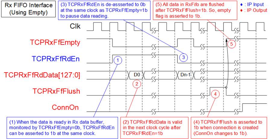
Figure 9: Rx FIFO interface timing diagram by using Empty flag
(1) Check the TCPRxFfEmpty flag to confirm data availability. When data is ready (TCPRxFfEmpty=0b), set TCPRxFfRdEn to 1b to read data from the Rx data buffer.
(2) The TCPRxFfRdData signal is valid in the next clock cycle.
(3) Reading data must be immediately paused by setting TCPRxFfRdEn=0b when TCPRxFfEmpty is equal to 1b.
(4) The user must read all data from the Rx data buffer before creating a new connection. When a new connection is established, all data in the Rx data buffer is flushed, and TCPRxFfFlush is set to 1b. Once the new connection is completed, the ConnOn value changes from 0b to 1b.
(5) After finishing the Flush operation, TCPRxFfEmpty is asserted to 1b.
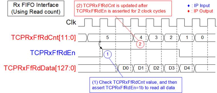
Figure 10: Rx FIFO interface timing diagram by using read counter
When the user logic reads data in burst mode, the TOE25G IP provides a read data counter signal to indicate the total amount of data stored in the Rx data buffer in 128-bit unit. For instance, in Figure 10, there are five units of data available in the Rx data buffer. Therefore, the user can set TCPRxFfRdEn to 1b for five clock cycles to read all the data from the Rx data buffer. The latency time to update TCPRxFfRdCnt after setting TCPRxFfRdEn to 1b is two clock cycles.
EMAC Interface
EMAC interface of TOE25G IP utilizes a 64-bit Avalon-stream interface, but it has a limitation that it cannot pause data transmission before transmitting the end of the packet. To transmit a packet, the MacTxReady must be asserted to 1b while transmitting a packet. However, once the final data of the packet has been transferred, MacTxReady can be de-asserted to 0b to pause the transmission of the next packet.
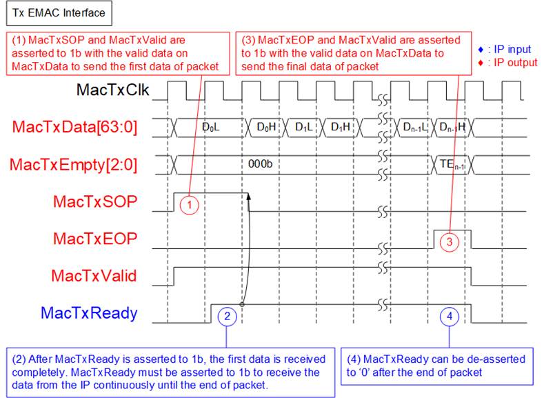
Figure 11: Transmit EMAC interface timing diagram
(1) TOE25G IP asserts MacTxSOP and MacTxValid to 1b with the first data of the packet. All signals are latched until MacTxReady is asserted to 1b to accept the first data.
(2) After the first data is accepted by EMAC, MacTxReady must remain set to 1b to accept all remaining data in the packet from the TOE25G IP until the end of packet. The IP sends all data of each packet continuously.
(3) MacTxEOP and MacTxValid are both asserted to 1b when the final data of the packet is transmitted.
(4) Once the end of the packet has been transferred, MacTxReady can be asserted to 0b to pause the transmission of the next packet.
(5)
The Receive EMAC interface also requires continuous receipt of packet data, similar to Transmit EMAC interface. The Valid signal must remain asserted at 1b from the start of the packet to the end of the packet without interruption, as shown in Figure 12.
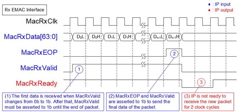
Figure 12: Receive EMAC Interface timing diagram
(1) The TOE25G IP detects the start of the receive frame when MacRxValid changes from 0b to 1b. In this cycle, the first data is valid on MacRxData. Afterward, MacRxReady is asserted to 1b to accept all data of this packet until the end of the packet. To continuously send data of each packet, MacRxValid must remain set to 1b.
(2) The end of the packet is detected when MacRxEOP=1b and MacRxValid=1b. In this cycle, the final data of the packet is valid on MacRxData.
(3) After the final data of the packet has been transferred, TOE25G IP de-asserts MacRxReady for 2 clock cycles to complete the packet post processing. Therefore, EMAC must support pausing the data packet transmission for 2 clock cycles.
However, the user interface of E-tile Hard IP may pause data transmission before the final data of each packet is transferred, which is incompatible with the continuous data transfer requirement of the TOE25G IP EMAC interface. Therefore, additional logic, including a small buffer, is necessary to store the data when the E-tile Hard IP is not ready to transfer the data in each packet.
On the other hand, if the system design of TOE25G IP utilizes the 25G Ethernet Intel FPGA IP, the soft IP, it can directly connect without additional logic.
Note: Typically, EMAC has at least two-clock cycle gap size between each received packet for receiving Ethernet FCS, EFD, and IFG.
Example usage
Client mode (SRV[1:0] = 00b)
The steps to set the registers for transferring data in Client mode are outlined below.
1) Set the RST register=1b to reset the IP.
2) Set the SML/SMH for MAC address, DIP/SIP for IP address, and DPN/SPN for port number.
Note: DPN is an optional setting when the port is opened by IP (Active open).
3) Set RST register=0b to start the IP initialization process. The TOE25G IP will send an ARP request packet to get the Target MAC address from the ARP reply packet. The Busy signal is de-asserted to 0b after completing the initialization process.
4) The new connection can be created by two modes.
a. Active open: Write CMD register = �Open connection� to create the connection (SYN packet is firstly sent by TOE25G IP). After that, wait until Busy flag is de-asserted to 0b.
b. Passive open: Wait until �ConnOn� signal = 1b (the target device sends SYN packet to TOE25G IP firstly).
5) a. For sending data, set TDL register (total transmit length) and PKL register (packet size). Then, set CMD register = �Send Data� to start data transmission. The user can send the data to TOE25G IP via the TxFIFO interface before or after setting the CMD register. Once the command is finished, the Busy flag is de-asserted to 0b. The user can set a new value to the TDL/PKL register and then set CMD register = �Send Data� to start the next transmission.
b. For receiving data, the user should monitor RxFIFO status and read the data until RxFIFO is empty.
6) Similar to creating the connection, the connection can be terminated by two modes.
a. Active close: Set CMD register = �Close connection� to close the connection (FIN packet is firstly sent by TOE25G IP). After that, wait until Busy flag is de-asserted to 0b.
b. Passive close: Wait until �ConnOn� signal = 0b (FIN packet is sent from the target to TOE25G IP firstly).
Server mode (SRV[1:0] = 01b)
1) Set RST register=1b to reset the IP.
2) Set SML/SMH for MAC address, DIP/SIP for IP address, and DPN/SPN for port number.
3) Set RST register=0b to begin the IP initialization process by waiting for an ARP request packet to get the Target MAC address. The IP then creates an ARP reply packet to return to the target device. Once the initialization process is completed, the Busy signal is de-asserted to 0b.
4) The remaining steps are the same as step 4 � 6 of Client mode.
Fixed MAC mode (SRV[1] = 1b)
In Fixed MAC mode, the MAC Address of the target device is loaded from DML and DMH register. The process for transferring data is the same as that of Client and Server mode. The following steps provides an example of how to run TOE25G IP in Fixed MAC mode.
1) Set RST register=1b to reset the IP.
2) Set SML/SMH for MAC address of TOE25G IP, DML/DMH for MAC address of the target device, DIP/SIP for IP address, and DPN/SPN for port number.
3) Set RST register=0b to begin the IP initialization process. Once initialization is completed, the busy signal will be de-asserted to 0b.
4) The remaining steps are the same as step 4 � 6 of Client mode.
PKL and TDL setting in Send command
When executing the Send command, the TOE25G IP can operate in two modes based on the value of TDL compared to N times of PKL. The details for each mode are described as follows.
TDL = N times of PKL
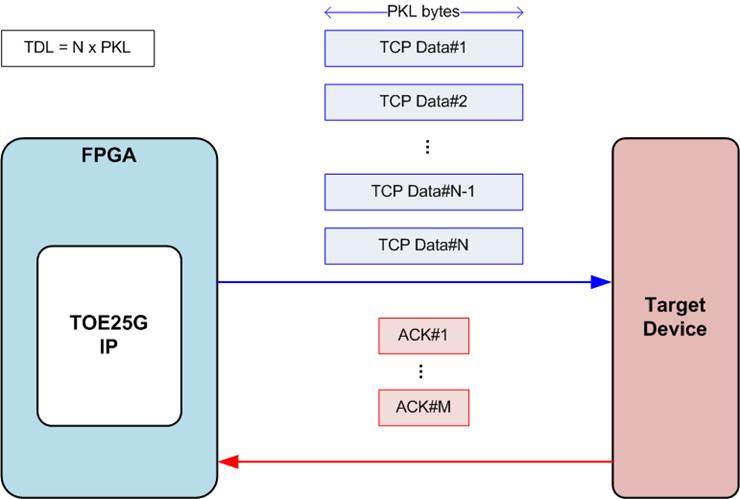
Figure 13: TCP packet when TDL = N times of PKL
If TDL value is equal to N times of PKL value, the user data is split into N packets and transmitted to the target device, as shown in Figure 13. If the target device responds with an ACK packet for each TCP packet, there will be N ACK packets in the network system. To improve network performance, several ACK packets can be combined into be one packet using the TCP delayed ACK technique. Therefore, the number of ACK packets returned from the target device (M) may be less than the number of data packets from TOE25G IP (N) when running the Send command. The PSH[0] value does not affect this condition. The last data packet (TCP Data#N) is sent only once.
TDL = N times of PKL + Residue
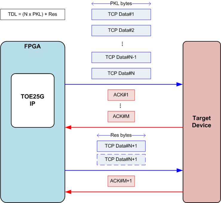
Figure 14: TCP packet when TDL = (N times of PKL) + Residue
If TDL value is not equal to N times of PKL value, the data sent to the target device is split into N packets of PKL-byte data and one last packet that contains Res-byte data, as shown in Figure 14. The first step is similar to the condition where TDL is equal to N times of PKL. The IP needs to receive an ACK packet from the target device to confirm that all N-packets have been received completely. After that, the last packet, which contains the residue byte data, is sent to the target device. If the PSH[0] register is set to 0b (default value), the residue packet is sent twice. Otherwise, the last packet is sent only once. The Send command is completed when the target returns an ACK to confirm that the last packet have been received.
Note: If target device is running on an OS that enables the delayed ACK feature, the ACK#M packet, which confirms the acceptance of TCP Data#N, may arrive too late due to timeout condition in some conditions. Therefore, the target device needs to disable the delayed ACK feature or the TDL value should be aligned to PKL value in systems that are sensitive to this latency time.
Connection termination of unusual case
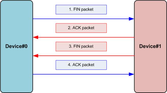
Figure 15: Terminate connection sequence
The process of terminating a connection in the normal case is illustrated in Figure 15, where four packets are exchanged between two devices. The first device (Device#0) initiates the connection termination by sending a FIN packet. If the second device (Device#1) agrees to terminate the connection, it responds with an ACK and FIN packet, which may be sent together in one packet or in separate packets. Finally, Device#0 confirms the termination by sending an ACK packet. The TOE25G IP can execute the close connection in two modes, Active and Passive. This section describes the operation of TOE25G IP in some unusual cases.
- In the Active mode, TOE25G IP sends a FIN packet to initiate the close and expects to receive ACK and FIN packets from the target. Assumed that a FIN packet sets sequence number (SeqNum) to be N and an acknowledge number (AckNum) to be M, the expected ACK and FIN packet must contain SeqNum=M and AckNum=N+1. If TOE25G IP does not receive the expected packets until timeout (set by the TMO register), it sends a RST packet to terminate the connection immediately without 16 retry times. TOE25G IP also asserts TimerInt and TMO[3] to 1b.
- If TOE25G IP receives new data from the target while executing the Active close command, it rejects the data and still waits for the expected ACK and FIN packets. Similar to the first case, if the expected packets are not received until the timeout, TOE25G IP sends the RST packet to terminate the connection.
- In the Passive mode, while TOE25G IP is transmitting data to the target, it receives a FIN packet from the target to terminate the connection. TOE25G IP sends an ACK and FIN packet in response, with SeqNum set to the most recently confirmed data acceptance value. After the termination of the connection, the ConnOn and Busy outputs are set to 0b. The user can check the amount of untransmitted data in the TDL register.
Verification Methods
The TOE25G IP Core functionality was verified by simulation and also proved on real board design by using Stratix10 GX, Stratix10 MX, and Agilex 7 F-series FPGA development board.
Recommended Design Experience
User must be familiar with HDL design methodology to integrate this IP into their design.
Ordering Information
This product is available directly from Design Gateway Co., Ltd. Please contact Design Gateway Co., Ltd. For pricing and additional information about this product using the contact information on the front page of this datasheet.
Revision History
|
Revision |
Date |
Description |
|
1.3 |
23-May-2023 |
Correct Figure6, PKL. Add TCPTxFfWrCnt signal, and Connection termination of unusual case section. |
|
1.2 |
11-Aug-2022 |
Support Agilex 7-F and add PKL/TDL setting in Send command topic |
|
1.1 |
4-Mar-2021 |
Support Stratix10 MX |
|
1.0 |
16-Sep-2020 |
New release |