
|
Core Facts |
|
|
Provided with Core |
|
|
Documentation |
User Guide, Design Guide |
|
Design File Formats |
Encrypted File |
|
Instantiation Templates |
Verilog |
|
Reference Designs & Application Notes |
Vivado Project, See Reference design manual |
|
Additional Items |
Demo on ZCU106, KCU116 board |
|
Support |
|
|
Support Provided by Design Gateway Co., Ltd. |
|
Design Gateway Co., Ltd
E-mail: ip-sales@design-gateway.com
URL: design-gateway.com
Features
· 10 Gbps WireGuard Engine
· Internal Handshake Support
· Encryption/Decryption: ChaCha20-Poly1305
· Key Derivation Function (KDF): BLAKE2s
· Key Exchange: X25519
· IPv4 Protocol Support without IP fragmentation
· Integrated UDP/IP and ARP Protocol Controllers
· Jumbo Frame Support
· Configurable Transmit Buffer Size: 16 kB or 64 kB
· Recommended Minimum User Clock Frequency: 160 MHz
· User Data Interface: 64-bit AXI4-Stream
· Ethernet MAC Interface: 64-bit AXI4-Stream
· Customizable Options:
· Additional buffer sizes
· Specified number of WireGuard sessions
Table 1 Table Description
|
Family |
Example Device |
Fmax (MHz)
|
CLB Regs
|
CLB LUTs
|
CLB1 |
DSP |
BRAMTile |
Design Tools |
|
Zynq-Ultrascale+ |
xczu7ev-ffvc1156-2-e |
160 |
15210 |
21444 |
4243 |
84 |
47.5 |
Vivado2022.1 |
|
Kintex UltraScale+ |
xcku5p-ffvb676-2-e |
160 |
15210 |
21437 |
4183 |
84 |
47.5 |
Vivado2022.1 |
Notes:
1) The actual logic resource depends on the percentage of unrelated logic.
2) Resource usage is based on a 64kB buffer size.
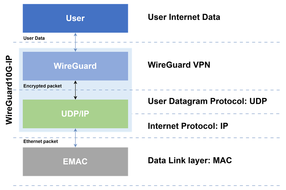
Figure 1 The WireGuard protocol architecture
General Description
WireGuard is a high-performance cryptographic transport protocol designed to provide secure, efficient, and lightweight connections between clients and servers over networks. Unlike traditional VPN protocols that rely on TCP/IP for reliable data transmission, WireGuard operates at the transport layer while incorporating modern cryptographic techniques to optimize performance and security.
The WireGuard protocol simplifies network stack complexity by consolidating security and transport functionalities into a single layer. This design allows for faster connection establishment, reduced latency, and improved throughput compared to legacy VPN solutions. Its streamlined architecture also enhances compatibility with modern networking environments, making it ideal for high-speed applications.
While WireGuard is increasingly adopted across industries-including cloud computing, IoT, and enterprise networks-its efficiency and simplicity have led to widespread integration in operating systems, routers, and security appliances. Major platforms such as Linux, Windows, and mobile operating systems now include native WireGuard support, reflecting its growing relevance in secure communications.
Our WireGuard 10Gbps IP Core (WireGuard10G-IP) is purpose-built to accelerate WireGuard protocol processing for high-speed applications. It handles critical functions such as:
· Key exchange and handshake using X25519 for elliptic curve cryptography.
· Data encryption/decryption via ChaCha20-Poly1305.
· Session management for secure peer-to-peer or client-server connections.
The core operates seamlessly at 10 Gbps line rates, enabling real-time encryption/decryption without compromising throughput. Prior to data transmission, the WireGuard10G-IP establishes a secure channel through a cryptographic handshake, ensuring mutual authentication and key agreement between peers. Only after a successful handshake does the core permit encrypted payload exchange, adhering to WireGuard’s security-first design.
This implementation aligns with the WireGuard protocol specifications as defined in the official documentation (e.g., https://www.wireguard.com/papers/wireguard.pdf).
Application Example
1. High-Speed VPN Gateway for Data Centers
The WireGuard Protocol is widely implemented in data center VPN gateways to provide secure, low-latency inter-server communication. Due to its efficient architecture capable of achieving high throughput (10 Gbps+ on optimized hardware), it ensures minimal overhead for bulk data transfers, making it ideal for:
· Cloud-to-Cloud Encryption: Establishing secure tunnels between different cloud providers (e.g., AWS-to-Azure secure connectivity).
· Database Replication: Securely synchronizing and replicating databases (e.g., MySQL, PostgreSQL) over encrypted channels.
· Microservices Communication: Protecting sensitive data exchanges between Kubernetes pods and containerized workloads.
2. Enterprise Remote Access
Enterprises are increasingly adopting the WireGuard Protocol within firewall appliances and SD-WAN routers to replace legacy VPNs (e.g., IPsec, OpenVPN) with a faster, more streamlined alternative. Key use cases include:
· Secure Employee Remote Access: Providing high-performance, encrypted connections for corporate laptops to access headquarters (HQ) resources.
· Branch Office Connectivity: Creating robust, encrypted site-to-site tunnels to link regional offices efficiently.
· IoT Device Provisioning: Securing communication for IoT deployments in smart factories and healthcare environments.
3. 5G and Telco Edge Computing
Telecom providers integrate the WireGuard Protocol into 5G User Plane Function (UPF) and Multi-access Edge Computing (MEC) nodes to enhance network performance:
· Line-Rate Encryption: Encrypting user plane traffic at high speeds, significantly reducing CPU bottlenecks common in older protocols.
· Reduced Latency for Real-Time Applications: Enabling the low-latency requirements of next-generation technologies like autonomous vehicles and AR/VR.
· Simplified Network Slicing: Utilizing lightweight cryptography to streamline the management of isolated network slices.
Functional Description
Figure 2 illustrates the WireGuard10G-IP block diagram and its interface signals. Users interact with the IP core via the signals described in Table 3.
· MAC Interfaces: The MAC Tx I/F and MAC Rx I/F connect to the Ethernet subsystem and operate at its clock frequency. These interfaces handle packet transfer between the IP core and the MAC layer.
· User Data Interface: The User Data Interface is implemented as a 64-bit AXI4-Stream and runs at a clock frequency not lower than the MAC interface frequency. This ensures seamless high-speed data transfer between the IP core and user logic.
· Internal Operations: The IP core handles control, encryption/decryption, and handshake operations. Configuration is managed through dedicated interfaces. The internal operations require a minimum clock frequency of 160 MHz for optimal performance.
To configure parameters and operate the IP, users interact with several specialized control interfaces. The Control Parameter interface covers both Network parameters (such as local IP and MAC addresses) and WireGuard parameters (such as Private Keys and Peer Public Keys). Real-time operational monitoring is handled through IP State and IP Status signals, which provide visibility into the current system phase and the outcome of internal events.
While monitoring via IP State and IP Status is sufficient for standard operations, these signals can also be used for advanced diagnostics to analyze handshake sequences or network-level issues. These status indicators ensure that debugging and system verification within the WireGuard10G-IP are straightforward and highly transparent.
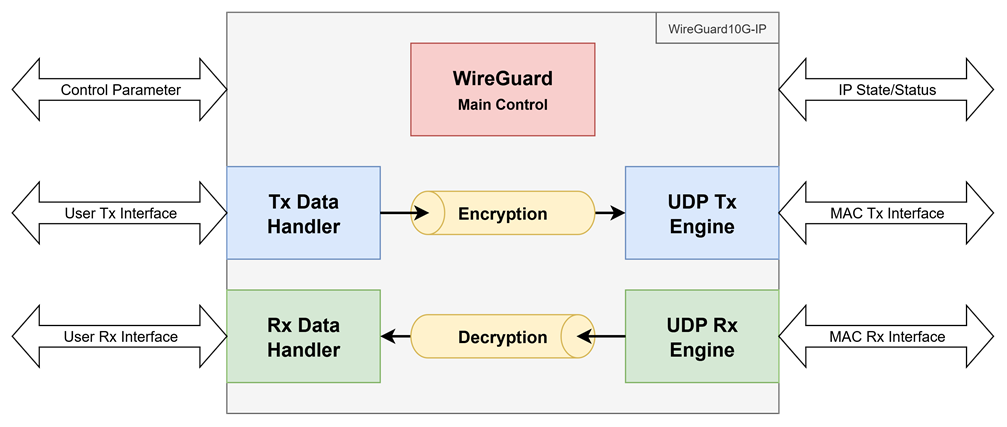
Figure 2 WireGuard10G-IP block diagram
Table 2 Core Parameters
|
Parameter name |
Value |
Description |
|
ClockPerMS |
1000-10000 |
Defines the number of clock cycles per 1 millisecond. This value is a mandatory requirement for the IP internal timers. |
|
BufferSize |
0-1 |
Specifies the User Buffer
transmission capacity: |
Table 3 WireGuard10G-IP Interface signals
|
Signal name |
Dir |
Description |
|
RstB |
In |
IP core system reset. Active low. |
|
UserClk |
In |
IP core system clock. |
|
Version [31:0] |
Out |
32-bit version number of IP |
|
Operation Control Interface |
||
|
WGActivate |
In |
User asserts to ‘1’ when parameters
are valid for activation. |
|
WGDeactivate |
In |
User asserts to ‘1’ to deactivate
the current session. |
|
WGAcceptConfig |
Out |
Asserts to ‘1’ when the IP Core is ready to accept a new configuration. |
|
TimeStampTAI64[63:0] |
In |
Current timestamp in TAI64 format (unit: seconds). Used for handshake initiation to prevent replay attacks. |
|
Tunnel Configuration Parameters |
||
|
DevicePrivateKey[255:0] |
In |
Defines the local host WireGuard Private Key. |
|
DevicePublicKey[255:0] |
Out |
Displays the local host WireGuard Public Key. Valid after IP initialization is completed. |
|
PeerPublicKey[255:0] |
In |
Defines the remote target WireGuard Public Key. |
|
PresharedKey[255:0] |
In |
Defines the WireGuard Pre-shared Key (PSK) for additional security. This value must be set to 0 if the PSK feature is disabled. |
|
PersistentKeepalive[15:0] |
In |
Defines the WireGuard Persistent Keepalive interval (in seconds). This value must be set to 0 to disable the keepalive feature. |
|
Network Configuration Parameters |
||
|
DeviceMacAddr[47:0] |
In |
Defines the local host MAC address. |
|
DeviceIPAddr[31:0] |
In |
Defines the local host IP address. |
|
DevicePort[15:0] |
In |
Defines the local host port number. |
|
EndPointMacAddr[47:0] |
Out |
Displays the remote target MAC address. Valid after IP initialization is completed. |
|
EndPointIPAddr[31:0] |
In |
Defines the remote target IP address. |
|
EndPointPort[15:0] |
In |
Defines the remote target port number. |
|
SubnetMask[4:0] |
In |
Subnet mask in CIDR notation format of WireGuard IP. Specifies the network prefix length for the local subnet. Valid Range: 0 to 31. |
|
GatewayIPAddr[31:0] |
In |
IP address of Gateway. This value must be set to 0.0.0.0 if there is no gateway in the system. |
|
Status Monitoring |
||
|
ExtractKeylogValid |
Out |
Asserts to ‘1’ when ExtractKeylog[255:0] is valid and available for extraction. |
|
ExtractKeylog[255:0] |
Out |
Provides the 256-bit Key material (such as the ephemeral session keys or internal state) for logging or external security auditing. |
|
IPStatusValid |
Out |
Asserts to ‘1’ when the IPStatus[15:0] are valid. |
|
IPStatus[15:0] |
Out |
Detailed status vector of the IP Core. |
|
IPState[3:0] |
Out |
Current operational state of the WireGuard State Machine. |
|
User Tx Data Interface (Synchronous to WGTxClk) |
||
|
WGTxClk |
In |
Clock signal synchronous to the User Tx interface. |
|
WGTxReady |
Out |
Asserted to ‘1’ when the core is ready to accept data. |
|
WGTxValid |
In |
Asserted to ‘1’ when WGTxData is valid. |
|
WGTxData[63:0] |
In |
Input data to be encrypted/processed by the WireGuard core. |
|
WGTxByteEn[7:0] |
In |
Byte enable of WGTxData. Valid when WGTxValid=‘1’. During packet transmission, this signal is equal to 0xFF for all data except the final data of the packet which can be: 0x01, 0x03, 0x07, 0x0F, 0x1F, 0x3F, 0x7F, or 0xFF when WGTxData[7:0], [15:0], [23:0], [31:0], [39:0], [47:0], [55:0], or [63:0] is valid respectively. |
|
WGTxLast |
In |
Asserted to ‘1’ with the final data of the packet on WGTxData. |
|
WGTxError |
In |
Asserted to ‘1’ to indicate an error in the current Tx frame. |
|
User Rx Data Interface (Synchronous to WGRxClk) |
||
|
WGRxClk |
In |
Clock signal synchronous to the User Rx interface. |
|
WGRxValid |
Out |
Asserts to ‘1’ when WGRxData is valid. |
|
WGRxData[63:0] |
Out |
Output data decrypted/processed by the WireGuard core. |
|
WGRxByteEn[7:0] |
Out |
Byte enable of WGRxData. Valid when WGRxValid=‘1’. During packet transmission, this signal is equal to 0xFF for all data except the final data of the packet which can be: 0x01, 0x03, 0x07, 0x0F, 0x1F, 0x3F, 0x7F, or 0xFF when WGRxData[7:0], [15:0], [23:0], [31:0], [39:0], [47:0], [55:0], or [63:0] is valid respectively. |
|
WGRxStart |
Out |
Asserted to ‘1’ with the first data of the packet on WGRxData. Valid when WGRxValid is asserted to ‘1’. |
|
WGRxLast |
Out |
Asserts to ‘1’ to indicate the final data of the packet. |
|
WGRxError |
Out |
Asserts to ‘1’ to indicate that the received frame contains an error (e.g., integrity check failure). Valid when WGRxLast=‘1’. |
|
MAC Tx Interface (Synchronous to MacTxClk) |
||
|
MacTxClk |
In |
Clock signal synchronous to the Tx MAC interface, used for 10G Ethernet operation. |
|
MacTxReady |
In |
Asserted to ‘1’ when MacTxData is being accepted. |
|
MacTxValid |
Out |
Asserted to ‘1’ when MacTxData is valid. |
|
MacTxData[63:0] |
Out |
Transmitted data of the IP to the Ethernet MAC. It is valid when ‘MacTxValid’ is set to ‘1’. |
|
MacTxByteEn[7:0] |
Out |
Byte enable of MacTxData. Valid when MacTxValid=‘1’. During packet transmission, this signal is equal to 0xFF for enabling all 64-bit data except the final data of the packet which can be equal to: 0x01, 0x03, 0x07, 0x0F, 0x1F, 0x3F, 0x7F, or 0xFF when MacTxData[7:0], [15:0], [23:0], [31:0], [39:0], [47:0], [55:0], or [63:0] is valid respectively. |
|
MacTxStart |
Out |
Asserted to ‘1’ with the first data of the packet on MacTxData. Valid when MacTxValid is asserted to ‘1’. |
|
MacTxLast |
Out |
Asserted to ‘1’ with the final data of the packet on MacTxData. Valid when MacTxValid is asserted to ‘1’. |
|
MAC Rx Interface (Synchronous to MacRxClk) |
||
|
MacRxClk |
In |
Clock signal synchronous to the Rx MAC interface, used for 10G Ethernet operation. |
|
MacRxValid |
In |
Asserts to ‘1’ to transfer MacRxData. |
|
MacRxData[63:0] |
In |
Received data from the Ethernet MAC. It is valid when MacRxValid is set to ‘1’. |
|
MacRxByteEn[7:0] |
In |
Byte enable of MacRxData. Valid when MacRxValid=‘1’. During packet transmission, this signal is equal to 0xFF for enabling all 64-bit data except the final data of the packet which can be equal to: 0x01, 0x03, 0x07, 0x0F, 0x1F, 0x3F, 0x7F, or 0xFF when MacRxData[7:0], [15:0], [23:0], [31:0], [39:0], [47:0], [55:0], or [63:0] is valid respectively. |
|
MacRxLast |
In |
Asserts to ‘1’ to indicate that this is the last data. |
|
MacRxError |
In |
Asserts to ‘1’ to indicate that this frame contains an error. This signal is valid when the last data is transferred, as indicated by MacRxLast=‘1’. |
· Activate WireGuard Session
The activation process of the WireGuard10G-IP core occurs after the user has configured all necessary system parameters. The operational sequence follows the UserClk timing as detailed in Figure 3.
When the system initializes, the WGAcceptConfig signal is asserted to ‘1’, indicating that the IP core is ready to receive a new configuration. The user must ensure that all parameters in the Tunnel Configuration such as DevicePrivateKey[255:0], PeerPublicKey[255:0], PresharedKey[255:0], and PersistentKeepalive[15:0] as well as the Network Configuration including DeviceIPAddr[31:0], DeviceMacAddr[47:0], DevicePort[15:0], SubnetMask[4:0], and GatewayIPAddr[31:0] are correctly defined and stable before activation.
The session activation begins when the user asserts the WGActivate signal to ‘1’ while WGAcceptConfig is still ‘1’. Upon detecting the assertion of WGActivate, the IP core de-asserts WGAcceptConfig to ‘0’. The user must maintain these parameter values without any changes until the IP initialization and ARP processes are complete. This completion is signaled when WGAcceptConfig returns to ‘1’. Simultaneously, the EndPointMacAddr[47:0] signal will display the remote target’s MAC address, and DevicePublicKey[255:0] will show the valid device public key.
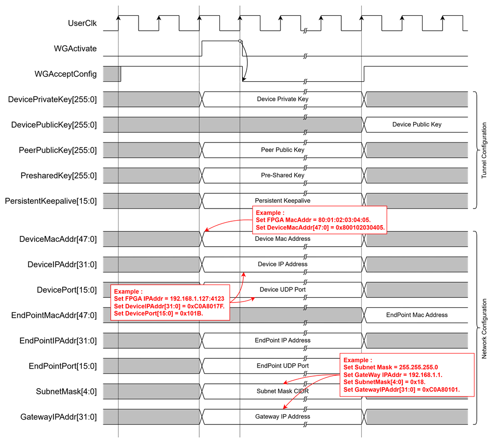
Figure 3 WireGuard10G-IP Activate and Configuration Timing Diagram
· Network Connectivity and ARP Management
WireGuard10G-IP establishes network connectivity by resolving the MAC address of the target device, which is essential for transmitting and receiving network packets. This resolution is handled by an integrated ARP (Address Resolution Protocol) manager within the IP core. The ARP manager operates during the network parameter configuration phase.
When the WGActivate signal is set to ‘1’, the IP’s internal controller initiates a verification of the GatewayIPAddr[31:0]. If GatewayIPAddr[31:0] is non-zero (not 0.0.0.0) and the EndPointIPAddr[31:0] is determined to be outside the local network based on the SubnetMask[4:0], the ARP protocol manager sends an ARP Request packet to the gateway via the connected network. It then waits for an ARP Reply from the gateway, as shown in the timing diagram in Figure 4.
Conversely, if the EndPointIPAddr[31:0] is within the local subnet, the ARP manager sends an ARP Request packet directly to the target device and waits for an ARP Reply to complete the process, as shown in Figure 5.
In both cases, if no ARP reply is received or if the reply is lost, the ARP manager will automatically retransmit the request packet up to 10 times. If no response is received after these attempts, the IP considers the target unreachable and will output a status code to the user via the IPStatus[15:0] signal to indicate that the WireGuard connection cannot be initiated due to the ARP failure.
It is important to note that during this ARP process, the IP will not initiate any WireGuard connections. The IP proceeds with the requested WireGuard connection only after the ARP process has successfully completed. This step ensures that all necessary network parameters are correctly configured and the destination is identified before any actual data transmission occurs.
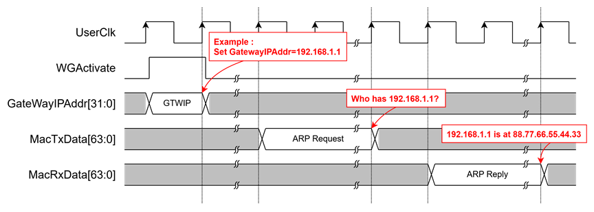
Figure 4 ARP Resolution via Gateway Timing Diagram
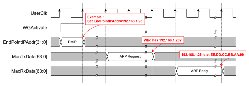
Figure 5 ARP Resolution for Local Subnet Timing Diagram
· Deactivate WireGuard Session
The deactivation process of the WireGuard10G-IP ensures a secure and orderly shutdown of the active session by clearing sensitive cryptographic material and flushing internal buffers to prevent data leakage or stale packet processing. This sequence is triggered when the WGDeactivate signal is asserted to ‘1’. The user must verify that the WGAcceptConfig signal is ‘1’ before setting WGDeactivate. During this process, the WGAcceptConfig signal is de-asserted to ‘0’ to prevent any new configuration from being applied while the system is shutting down.
Upon initiation, the IP core immediately destroys all encryption keys to reject any further data transmission or reception. The IP core then waits for the internal security engine to complete processing any remaining data before disabling the user transmit interface to prevent new data from entering. Subsequently, the IP core ensures all communication buffers are cleared. It waits for all pending packets to be transmitted and confirms that the UDP transmit buffers are completely empty. Once the transmit path is cleared, the core enables a UDP rejection mechanism to block incoming network data and ensures all previously received packets are fully processed or discarded, including stale handshake metadata.
Finally, after verifying that the internal user data paths are empty, the core resets all internal device states and parameters to their default values. Once the shutdown sequence is successfully finalized, the WGAcceptConfig signal is re-asserted to ‘1’, indicating that the IP core is ready for a clean reconfiguration and the initiation of a new session. The completion of this process is reported to the user via the IPStatus[15:0] signal.
· TAI64 Timestamp Management
To comply with the WireGuard protocol’s requirements for preventing Replay Attacks, the IP Core must be provided with a valid timestamp via the TimeStampTAI64[63:0] signal. The following details outline the specifications and implementation requirements:
TAI64 Standard and Format
TAI (Temps Atomique International) is an international atomic time standard that does not include leap seconds, unlike UTC. The WireGuard protocol utilizes the TAI64 64-bit (8 octets) format to identify precise moments in time:
· Bits [63:0]: Represents seconds elapsed since January 1, 1970 (Unix Epoch), with an initial offset of 262.
· The TAI64 value at the epoch (1970-01-01 00:00:00 TAI) is 0x4000000000000000.
· Using TAI64 ensures the responder can verify that a received handshake initiation message is fresh and contains a timestamp strictly greater than any previously received message from the same peer.
Implementation Logic for Users
Since the IP Core is designed on an FPGA architecture optimized for high-performance packet processing, the user is responsible for generating and controlling the TimeStampTAI64[63:0] signal:
· Synchronous Operation: The TimeStampTAI64[63:0] signal must be strictly synchronized with the UserClk. This ensures the IP Core can accurately sample the time value at the exact moment it constructs the handshake packet.
· Monotonic Counter: The user must implement a monotonic counter or interface with an internal Real-Time Clock (RTC) within the FPGA. This counter must continuously progress forward and must never regress to a lower value, even after a system reset (unless a new external time synchronization occurs).
· Precision: While the global TAI64N standard includes nanoseconds, this inputs signal focuses on the 64-bit seconds component to satisfy the protocol’s requirements for message freshness.
· WireGuard Handshake Process
The WireGuard10G-IP handshake process is the primary mechanism for establishing a high-security encrypted tunnel. It utilizes a 1-RTT (One Round-Trip Time) key exchange based on the Noise_IK handshake pattern, designed to minimize latency and ensure identity hiding (privacy) for both peers.
Cryptographic Protocols & Key Exchange
The IP Core implements industry-standard cryptographic primitives for each stage of the connection:
· Curve25519 (ECDH): Used for Elliptic Curve Diffie-Hellman key exchange to establish a shared secret.
· ChaCha20: The primary stream cipher for high-speed data encryption, optimized for FPGA architectures.
· Poly1305: Used for Message Authentication Code (MAC) to ensure data integrity and prevent tampering.
· BLAKE2s: A high-speed hashing function used for Key Derivation and cookie generation to mitigate DoS attacks.
Detailed Handshake Sequence
The operational sequence between the Initiator (FPGA) and the Responder (Peer), as illustrated in Figure 6, consists of the following steps:
1. Handshake Initiation
Once the ARP process is complete and WGActivate is set to ‘1’, the IP Core sends the first message. This contains the Ephemeral Public Key, the encrypted Static Public Key of the device, and an Encrypted Timestamp to prevent replay attacks. It also includes MAC1 values for DoS protection.
2. Handshake Response & DoS Protection
Upon successful verification, the Responder sends back a second message. This includes the Responder’s Ephemeral Public Key and an encrypted Empty Payload, which confirms that both parties have derived the same shared secret. Under high load, the Responder may instead send a Cookie Reply, requiring the Initiator to resend the Handshake Initiation with a MAC2 value to prevent DoS attacks.
3. Key Derivation & Transport Data
Both parties pass the exchanged values through an HKDF (HMAC-based Extract-and-Expand Key Derivation Function) to generate the Sending Key and Receiving Key. The system then enters the Transport Data Phase, where actual data is encrypted and transmitted using ChaCha20-Poly1305.
Operational Logic in IP Core
· Automatic Trigger: The system automatically initiates the handshake immediately after network parameter configuration is finalized and stops only when WGDeactivate is signaled.
· Persistent Keepalive: If the PersistentKeepalive[15:0] signal is configured (in seconds), the IP Core will automatically transmit keepalive packets to the Peer if no data has been exchanged within that interval. This maintains an active connection and ensures that devices behind NAT or Firewalls can consistently receive data from the Peer.
· State Management: The IP Core manages rekeying automatically every 2 minutes or after a specific volume of data has been transmitted, adhering to the RFC standard. This requires no additional control signals from the user.
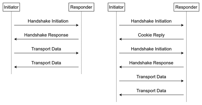
Figure 6 WireGuard Handshake and Transport Data Sequence
· User Data Interface
The user interface of the WireGuard10G-IP uses a simple streaming data interface similar to the AXI4-Stream interface, which is used to transmit and receive packets.
When the user requests to send a packet, it sets WGTxValid to ‘1’ along with the valid values for WGTxData, WGTxByteEn, and WGTxLast. The user must be paused if WGTxReady is de-asserted to ‘0’ at any clock cycle and resumed afterward. The user can also pause the process by de-asserting WGTxValid to ‘0’ at any clock cycle and resuming afterward. WGTxByteEn[7:0] indicates which bytes within WGTxData[63:0] are valid. For example, WGTxByteEn[0] indicates the validity of WGTxData[7:0], and WGTxByteEn[1] for the validity of WGTxData[15:8], while WGTxLast is asserted to indicate the end of a packet. If the user wants to cancel the current packet, the user must assert WGTxError together with WGTxLast. Figure 7 depicts an example of sending a packet.
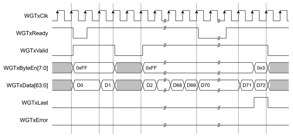
Figure 7 User Data Transmit Timing Diagram
On the other hand, Figure 8 shows the interface also handles the receiving of packets. To start receiving a packet, WGRxValid is asserted to indicate valid data on WGRxData[63:0]. WGRxByteEn[7:0] is used to indicate which bytes within WGRxData[63:0] are valid, WGRxStart is asserted to indicate the start of a packet, and WGRxLast is asserted to indicate the end of a packet. If an error occurs during reception, WGRxError will be asserted to ‘1’ at the end of the packet, and the receiving packet must be discarded.
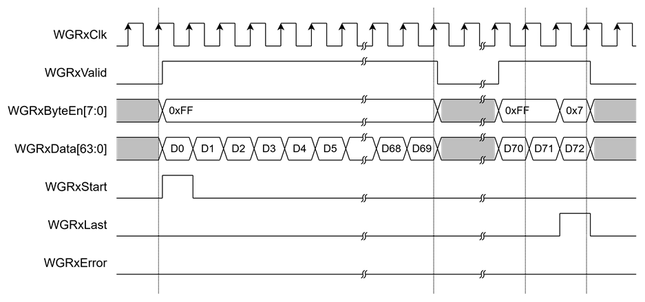
Figure 8 User Data Receive Timing Diagram
· User Data Interface and Protocol Constraints
This section describes the data handling mechanisms of the WireGuard10G-IP and the specific requirements for the data entering the user interface.
Layer 3 Data Encapsulation
The WireGuard protocol is designed to encapsulate Layer 3 (L3) IP packets. It is important to note that the WireGuard10G-IP core functions as a secure tunnel for L3 traffic; however, the Routing Table and IP Forwarding logic which determine which packets should be sent through the tunnel are not handled by this IP core. The user must implement or provide the necessary L3 routing logic to feed the appropriate packets into the user data interface.
IP Fragmentation and MTU Requirements
The WireGuard10G-IP core does not support IP Fragmentation, neither for transmission (TX) nor reception (RX).
· TX Direction: If the user provides a packet that, after WireGuard encapsulation, exceeds the network’s MTU, the packet may be dropped by intermediate routers.
· RX Direction: The IP core cannot reassemble fragmented WireGuard UDP packets received from the network.
User Action: Users must configure the MTU of the WireGuard interface on the Peer side (e.g., Linux, Windows, or Router) to a value that accounts for the WireGuard overhead to ensure packets remain within the physical network limits.
Jumbo Frame Support and Packet Processing
The IP core supports Jumbo Frames to maximize throughput in high-speed environments.
· Maximum Packet Size: The user interface can accept a data stream with a maximum packet size of 8928 bytes. Any packet exceeding this limit will be discarded by the IP core.
· 1-to-1 Mapping: Every packet entering the user interface is encrypted and transmitted as a single WireGuard Transport Packet. The IP core does not perform packet aggregation or coalescing.
User MTU Calculation:
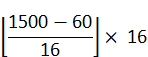
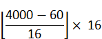
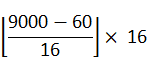
Users must calculate the MTU for incoming user data by subtracting the WireGuard overhead from the Physical Network MTU. The overhead includes the IPv4 Header (20 bytes), UDP Header (8 bytes), and the WireGuard Transport Header/Tag (32 bytes), totaling 60 bytes.
To ensure the integrity of the data stream and prevent processing errors within the IP Core, the recommended User MTU must be a value that is strictly divisible by 16. If the calculated value is not divisible by 16, it must be rounded down to the nearest multiple of 16 to maintain proper alignment with the protocol’s block-based encryption and padding requirements.
Table 4 Recommended User MTU based on Physical Network MTU
|
Physical MTU |
Calculation (Strictly Divisible by 16) |
Recommended User MTU |
|
Standard (1500) |
|
1440 bytes |
|
Medium (4000) |
|
3936 bytes |
|
Jumbo (9000) |
|
8928 bytes |
Decryption and Padding Handling
When the IP core decrypts a packet (RX), it does not remove the internal padding. According to the WireGuard specification, packets are padded to the nearest 16-byte boundary to hide the exact size of the original data.
Since the IP core does not parse the internal L3 payload length, the data delivered to the user interface will include these padding bytes. The user’s downstream L3 stack (e.g., an IPv4 or IPv6 parser) must use the Total Length field within the decrypted IP header to identify the actual end of the data and ignore the trailing padding.
· IP Status and State Indicators
This section describes the monitoring of the WireGuard10G-IP operations via the IPStatus[15:0] and IPState[3:0] signals. The system validates the status data using the IPStatusValid signal. When IPStatusValid is asserted to ‘1’, the user can read these signals to analyze the current system behavior and transition results.
IP State Indicators
The IPState[3:0] signal indicates the current operational phase of the IP Core, providing visibility into which stage of the protocol is currently being executed.
Table 5 IP Core State Definitions
|
Code |
State Label |
Description |
|
0x0 |
|
Initializing internal logic after Reset. |
|
0x1 |
|
System is ready and waiting for the WGActivate signal. |
|
0x2 |
|
Establishing UDP socket and configuring network parameters. |
|
0x3 |
|
Generating a Handshake Initiation packet (Initiator mode). |
|
0x4 |
|
Generating a Handshake Response packet (Responder mode). |
|
0x5 |
|
Processing a Handshake Initiation packet received from a Peer. |
|
0x6 |
|
Processing a Handshake Response packet received from a Peer. |
|
0x7 |
|
Handling Cookie Reply data for DoS protection. |
|
0x8 |
|
Performing deactivation and clearing internal buffers/memory. |
IP Status Codes
The IPStatus[15:0] signal provides details regarding the outcome of events occurring within each state, including success confirmations and technical error codes.
Table 6 IP Status Code Descriptions
|
Code |
Status Label |
Description |
|
Initial Setup & ARP |
||
|
0x0001 |
WG_INITIAL_UDP_SUCCESS |
UDP socket bound successfully (initial setup). |
|
0x0002 |
WG_INITIAL_ARP_FAILED |
ARP resolution failed for the peer IP address. |
|
0x0003 |
WG_INITIAL_DEV_FAILED |
WireGuard device creation or initialization failed. |
|
0x0004 |
WG_TIMER_TAI64_FAILED |
TAI64 timestamp failed consistency check (milliseconds out of range >= 1023 or max retries exceeded). |
|
Handshake Processing |
||
|
0x0011 |
WG_PROC_HSK_RES_SUCCESS |
Handshake response processed successfully. |
|
0x0012 |
WG_PROC_HSK_RES_BADPACK |
Malformed or invalid handshake response packet. |
|
0x0013 |
WG_PROC_HSK_RES_BADPEER |
Handshake response from unknown/unregistered peer. |
|
0x0014 |
WG_PROC_HSK_RES_BADMAC |
Handshake response MAC verification failed (tampered or wrong key). |
|
0x0021 |
WG_PROC_HSK_INT_BADPACK |
Malformed or invalid handshake initiation packet. |
|
0x0022 |
WG_PROC_HSK_INT_BADMAC |
Handshake initiation MAC verification failed. |
|
Handshake Creation (TX) |
||
|
0x0031 |
WG_CREA_HSK_INT_SUCCESS |
Handshake initial successfully generated |
|
0x0032 |
WG_CREA_HSK_INT_FAILED |
Failed to generate handshake initial (e.g., crypto failure) |
|
0x0033 |
WG_CREA_HSK_RES_SUCCESS |
Handshake response successfully generated. |
|
0x0034 |
WG_CREA_HSK_RES_FAILED |
Failed to generate handshake response (e.g., crypto failure). |
|
0x0035 |
WG_CREA_HSK_RES_FULL |
No space left to generate new handshake responses. |
|
Cookie & Key Management |
||
|
0x0041 |
WG_PROC_CKK_REP_SUCCESS |
Cookie reply processed successfully. |
|
0x0042 |
WG_PROC_CKK_REP_FAILED |
Failed to process cookie reply. |
|
0x0043 |
WG_PROC_CKK_REP_BADPEER |
Cookie reply from unknown/unregistered peer. |
|
0x0051 |
WG_PROC_KEYPAIR_SUCCESS |
Key pair processed successfully. |
|
0x0052 |
WG_PROC_KEYPAIR_DESTROY |
Key pair rejected/destroyed successfully. |
|
Deactivation Sequence |
||
|
0x0060 |
WG_DEACTIVATE_START |
Deactivation process started. |
|
0x0061 |
WG_DEACTIVATE_DISDATA |
Disconnecting user data interface. |
|
0x0062 |
WG_DEACTIVATE_CLRTX |
Transmit queue cleared successfully. |
|
0x0063 |
WG_DEACTIVATE_CLRRX |
Receive queue cleared successfully. |
|
0x0064 |
WG_DEACTIVATE_CLRPARAM |
Peer parameters cleared from memory. |
|
0x0065 |
WG_DEACTIVATE_SUCCESS |
Deactivation completed successfully. |
· MAC Interface
The MAC interface of the WireGuard10G-IP uses simple streaming data interface similar to the AXI4-Stream interface. It is used to transmit and receive packets, which are reduced Ethernet frames. According to IEEE 802.3, this reduced frame includes only the destination address, source address, length and data.
When the WireGuard10G-IP requests to send a packet, it sets MacTxValid to ‘1’ along with the valid values of MacTxData, MacTxStart, MacTxLast and MacTxByteEn. The transmission can be paused if MacTxReady is de-asserted to ‘0’ at any clock cycle and resumed afterward. MacTxByteEn[7:0] indicates which bytes within MacTxData[63:0] are valid. For example, MacTxByteEn[0] indicates the validity of MacTxData[7:0], and MacTxByteEn[1] for the validity of MacTxData[15:8]. MacTxStart is set to indicate the start of a packet, while MacTxLast is asserted to indicate the end of a packet. Figure 9 depicts an example of sending a packet.
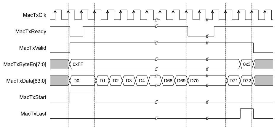
Figure 9 Transmit MAC Interface timing diagram
On the other hand, Figure 10 shows an example of receiving a packet. To start receiving a packet, MacRxValid is asserted to indicate valid data on MacRxData[63:0]. MacRxByteEn[7:0] is used to indicate which bytes within MacRxData[63:0] are valid, and MacRxLast is asserted to indicate the end of a packet. If an error occurs during reception, MacRxError will be asserted to ‘1’ at the end of the packet, and the receiving packet will be discarded. In this example, the reception of data (D0 to D72) happens when MacRxValid is asserted.
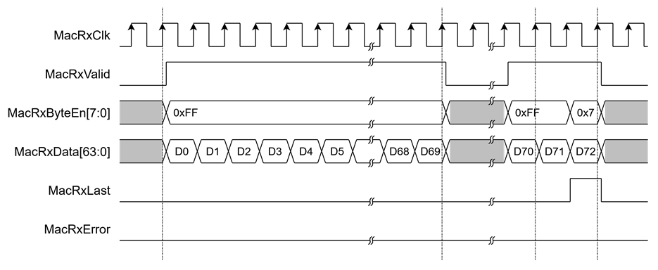
Figure 10 Receive MAC Interface timing diagram
Verification Methods
The WireGuard10G IP Core functionality was verified by simulation and also proved on real board design by using ZCU106 and KCU116 Evaluation Board.
Recommended Design Experience
The user must be familiar with HDL design methodology to integrate this IP into a system.
Ordering Information
This product is available directly from Design Gateway Co., Ltd. Please contact Design Gateway Co., Ltd. For pricing and additional information about this product, use the contact information on the front page of this datasheet.
Revision History
|
Revision |
Date (D-M-Y) |
Description |
|
1.00 |
8-May-26 |
Initial release |