WireGuard1G-IP Demo Instruction
4 FPGA Development Board Setup
5.5 Initialize TAI64 Timestamp
5.7 Set WireGuard Interface IP Address
5.13 Show Ephemeral Private Key
6.1 Point-to-Point Encapsulation using Nios Command Shell
6.1.2 WireGuard Peer Configuration
6.2 Selective Encapsulation using GUI
6.2.1 Graphical User Interface (GUI)
6.2.2 Connect with FPGA device
6.2.4 WireGuard Peer Configuration
6.2.5 Edit Tunnel Configuration
7.1 PC to PC via WireGuard1G-IP
This document provides a comprehensive guide for demonstrating the WireGuard1G IP core designed for 1 Gigabit Ethernet using FPGA evaluation boards. The WireGuard1G-IP core implements the modern and high-performance WireGuard VPN protocol to establish fast and secure network tunnels through hardware-based processing. Users will find step-by-step instructions for setting up the necessary software on a PC, configuring the FPGA device, and verifying the tunnel’s operation using either a Nios Command Shell or the provided graphical user interface (GUI) application.
The initial part of the guide focuses on the hardware environment and host PC preparation, covering essential network configuration details such as speed, duplex settings, and other network properties required for 1 Gbps operation. This is followed by detailed procedures for installing the WireGuard software on a PC and programming the FPGA evaluation board.
The final sections of this document describe the operational commands and demonstration scenarios available for the IP core. It includes a full reference of Nios Command Shell commands for manual configuration, along with walkthroughs for both point-to-point Nios Command Shell setups and selective encapsulation using the GUI application. Additionally, the document concludes with performance benchmarks using iperf3 to provide a clear comparison between software-based WireGuard and the hardware-accelerated IP core.
1 Environment Setup
To operate WireGuard1G-IP demo, please prepare the following test environment.
1) FPGA development board.
2) User PC and Endpoint PC with 1 Gigabit Ethernet or connecting with 1 Gigabit Ethernet card.
3) 2x1 Gb Ethernet cable: Cat5e or Cat6 cable to connect the FPGA to the PC.
4) Micro USB cable for JTAG connection between FPGA board and User PC.
5) Quartus Programmer and Nios Command Shell, installed on PC.
6) Demo configuration file (To download this file, please visit our web site at www.design-gateway.com).
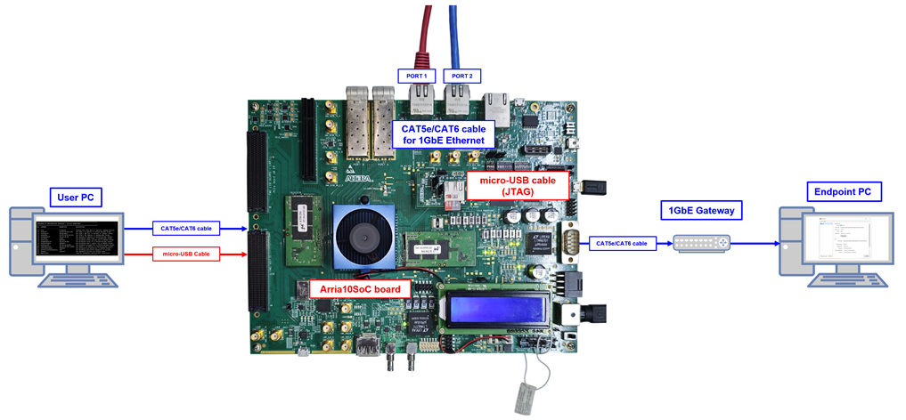
Figure 1 WireGuard1G-IP demo environment on A10SoC board
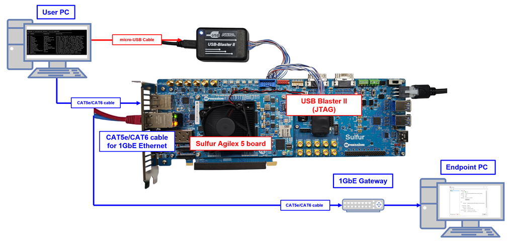
Figure 2 WireGuard1G-IP demo environment on Sulfur Agilex 5 E-Series board
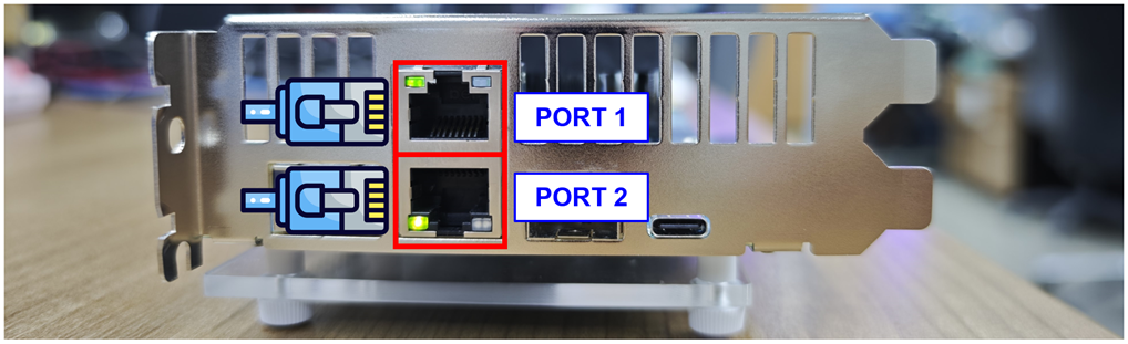
Figure 3 RJ45 connector location on the Sulfur Agilex 5 E-Series board
Note: In this demo, PORT1 is assigned to the User PC, while PORT2 is assigned to the 1GbE Gateway.
2 PC Setup
Before running demo, please check the network setting on PC. The example of setting 1 Gb Ethernet connection is described as follows.
2.1 Speed and Duplex Setting
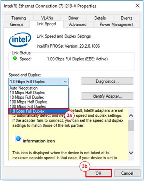
Figure 4 Set Link Speed = 1 Gbps
1) On Link Speed Tab, select “Speed and Duplex”. Set the value to “1.0 Gbps Full Duplex” for running 1.0 Gigabit transfer test, as shown in Figure 4.
3 WireGuard Software Setup
WireGuard is a modern, open-source VPN protocol known for its simplicity, high performance, and strong cryptographic design. This section provides an example of configuring the WireGuard software for use with the demo.
3.1 Install WireGuard
To install WireGuard on the PC:
1) Download the WireGuard Windows installer from https://www.wireguard.com/install.
2) Run the installer and follow the on-screen instructions.
3) Once installed, the WireGuard application will be available in the system tray and Start menu.
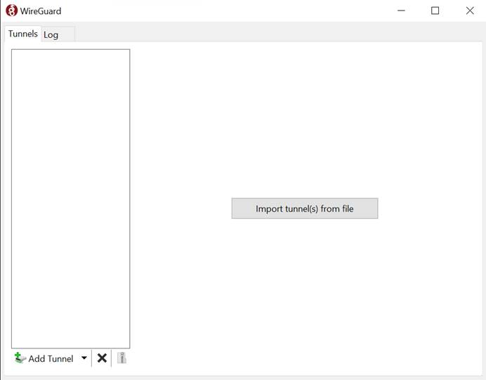
Figure 5 WireGuard application on Windows
3.2 Set up WireGuard
1) Open the WireGuard application and click “Add Tunnel” > “Add empty tunnel...”. A key pair will be automatically generated, with the private key pre-filled in the configuration editor.
2) Copy the displayed public key, as it will be required when configuring the FPGA demo. Complete the configuration by filling in the remaining fields as shown below.
[Interface]
PrivateKey = <Device private Key>
Address = <Tunnel IP, e.g. 10.0.0.1/32>
ListenPort = <Optional Listen Port, default: 51820>
MTU = <Optional MTU, default: 1420>
[Peer]
PublicKey = <Peer Public Key>
AllowedIPs = <Allowed IP, e.g. 10.0.0.3/32>
Endpoint = <Optional Peer endpoint, e.g. 192.168.7.25:51820>
PresharedKey = <Optional Preshared Key>
PersistentKeepalive = <Optional Keepalive Interval in Seconds>
3) Save the tunnel configuration, then click “Activate” to start the WireGuard interface. The status will change to “Active” once the interface is successfully running.
4) Once the tunnel is active, verify that the connection has been successfully established by checking the “Latest handshake” status. In the tunnel details panel shown in Figure 6
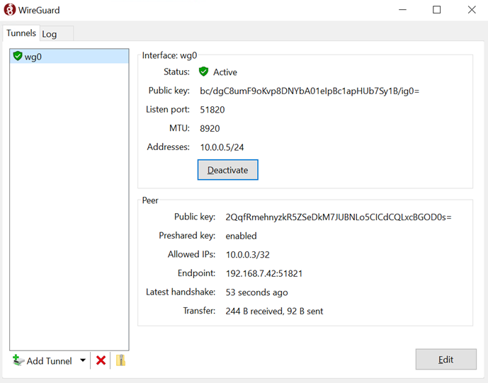
Figure 6 WireGuard Tunnel Handshake Successful
4 FPGA Development Board Setup
1) Make sure power switch is off and connect power supply to FPGA development board.
2) Connect USB cables between FPGA board and PC via micro-USB ports.
3) Turn on power switch for FPGA board.
4) Open Quartus Programmer to program FPGA through USB-1 by following step.
i) Click “Hardware Setup…” to select
- USB-BlasterII [USB-1]
ii) Click “Auto Detect” and select FPGA number.
iii) Select FPGA device icon.
iv) Click “Change File” button, select SOF file in pop-up window and click “open” button.
v) Check “program”.
vi) Click “Start” button to program FPGA.
vii) Wait until Progress status is equal to 100%.
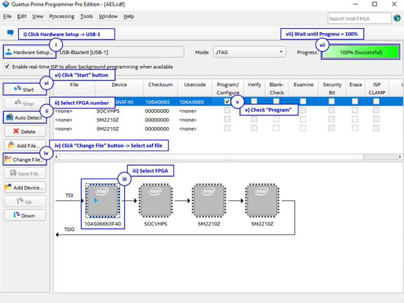
Figure 7 Program Device
After program SOF file complete, Quartus Prime will show popup message of Intel FPGA IP Evaluation Mode Status as shown in Figure 8. Please do not press cancel button.
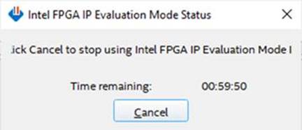
Figure 8 Intel FPGA IP Evaluation Mode Status
5 Command Details
To launch the FPGA console using the command shell. Run the following command:
- For Nios II command shell >> nios2-terminal.exe
- For Nios V command shell >> juart-terminal.exe
Users can set WireGuard1G-IP parameters by entering commands in the Nios command shell. When the FPGA boots, the available commands and their usage are displayed, as shown in Figure 9. Detailed information about each command is described below
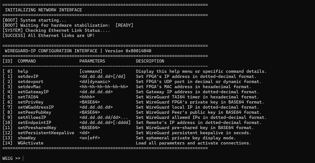
Figure 9 Nios V Command Shell
5.1 Set FPGA IP Address
> setdevIP <ddd.ddd.ddd.ddd>[/ddd]
This command sets the FPGA’s IP address in dotted-decimal format, with an optional subnet mask in CIDR notation. The default subnet mask is /24. This is the IP address of the physical Ethernet interface, not the WireGuard tunnel address.
5.2 Set FPGA Port Number
> setdevport <ddddd|dynamic>
This command is used to set the FPGA’s UDP source port number. If a numeric value (0–65535) is provided, it is used as a fixed static port. If the argument is dynamic, a dynamic port starting from 51821 is automatically assigned and incremented for each new connection. The default mode is dynamic.
5.3 Set FPGA MAC Address
> setdevMac <hh-hh-hh-hh-hh-hh>
This command is used to set the FPGA’s Ethernet MAC address in hexadecimal format, with octets separated by hyphens. The default FPGA MAC address is 80-11-22-33-44-55, which is a unicast MAC address.
5.4 Set Gateway IP Address
> setgatewayIP <ddd.ddd.ddd.ddd>
This command sets the network gateway IP address in dotted-decimal format.
5.5 Initialize TAI64 Timestamp
> setTAI64 <hhhhhhhhhhhhhhhh>
This command initializes the TAI64 timestamp used in the WireGuard handshake initiation message. The value must be a 16-character hexadecimal string representing the current TAI64 timestamp.
* TAI64, a timestamp format that represents time as the number of seconds since January 1, 1970 (TAI), encoded as a 64-bit big-endian integer.
5.6 Set FPGA Private Key
> setprivkey <BASE64>
This command sets the FPGA’s WireGuard private key. The key must be a valid 32-byte X25519 key encoded in Base64 (44 characters ending with ‘=’).
5.7 Set WireGuard Interface IP Address
> setWGaddressIP <ddd.ddd.ddd.ddd>
This command sets the IP address assigned to the FPGA’s WireGuard IP address. This is the IP address used for communication within the VPN tunnel, separate from the physical Ethernet interface IP.
5.8 Set Peer Public Key
> setpeerpubkey <BASE64>
This command is used to set the FPGA’s WireGuard Peer public key. The key must be the Base64-encoded X25519 public key that corresponds to the peer’s private key configured in the WireGuard peer’s configuration file.
5.9 Set Allowed IPs
> setallowsIP <ddd.ddd.ddd.ddd/ddd>...
This command sets the list of IP/CIDR pairs that are allowed to be routed through the WireGuard1G-IP (up to 16 entries, space-separated). Each entry may include a CIDR prefix; if omitted, /32 is used by default. Setting 0.0.0.0/0 routes all traffic through the IP.
5.10 Set Endpoint IP Address
> setendpointIP <ddd.ddd.ddd.ddd>[:ddddd]
This command sets the WireGuard peer’s endpoint IP address and port number separated by a colon. If the port is omitted, the default value of 51820 is used. The FPGA will initiate the WireGuard handshake to this endpoint.
5.11 Set Preshared Key
> setpresharedkey <BASE64>
This optional command sets a 32-byte symmetric pre-shared key (PSK) shared between the FPGA and Peer, encoded as a 44-character Base64 string.
5.12 Set Persistent Keepalive
> setpersistentkeepalive <ddddd>
The User sets the interval in seconds for persistent keepalive packets to ensure the bidirectional connection remains active through NAT or stateful firewalls. The User must provide a value within the valid 16-bit range, specifically from 0 to 65535 seconds. Setting the value to 0 allows the User to disable this feature, which is the default system state.
5.13 Show Ephemeral Private Key
> showkey <on|off>
This command enables or disables showkey mode, which controls whether the ephemeral private key is displayed on the Nios Command Shell. Set the parameter to “on” to enable or “off” to disable. This is disabled by default.
5.14 Activate WireGuard
> WGActivate
This command applies all previously configured parameters and initiates the WireGuard handshake with the configured Peer endpoint. Once the handshake completes successfully, the IP core enters the monitoring loop and continuously reports status codes and transfer statistics on the Nios Command Shell. User can press “Ctrl + X” to exit the monitoring loop and deactivate Wireguard.
6 Demo environment
This section describes the hardware and software environments used to demonstrate the WireGuard1G IP core. Two demo configurations are provided, each targeting a different use case.
The first, described in Section 6.1, uses the Nios Command Shell to configure and activate the FPGA directly, demonstrating a point-to-point WireGuard tunnel between the User PC and an Endpoint PC.
The second, described in Section 6.2, uses the provided GUI application to configure the FPGA, demonstrating selective encapsulation where only traffic from a specific IP address is encrypted and tunneled to the Endpoint PC.
Both configurations share the same FPGA board and PC hardware, but differ in network topology and configuration method.
6.1 Point-to-Point Encapsulation using Nios Command Shell
The testing environment for the Nios Command Shell demo is illustrated in Figure 10. The setup consists of three main components: the User PC, the FPGA board running the WireGuard1G IP core, and the Endpoint PC.
The User PC connects directly to the FPGA over a 1 GbE link. Its network interface is configured with a WireGuard tunnel address of 10.0.0.3 and a gateway of 10.0.0.1 as shown in Figure 11. Since all WireGuard tunnel traffic is routed through this gateway, the ARP table on the User PC must be manually configured for the gateway IP 10.0.0.1. Additionally, one active Ethernet interface must be reserved to support the Kill Switch or multiple allowed IPs functionality.
The FPGA is assigned a Network IP address of 192.168.7.42 with a gateway of 192.168.7.1. For outgoing packets sourced from the tunnel IP, it encapsulates and encrypts them into WireGuard packets before forwarding. For incoming packets, it decrypts and decapsulates them before delivering to the User PC. All WireGuard tunnel traffic is routed through the gateway to reach the Endpoint PC.
On the other side, the Endpoint PC is reachable at 203.0.113.5 on the network and is assigned a WireGuard tunnel IP of 10.0.0.5. The tunnel is established between the FPGA and the Endpoint PC through the gateway.
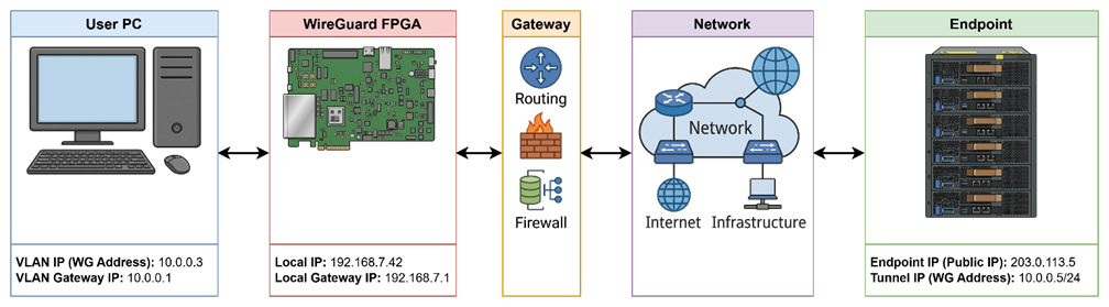
Figure 10 Nios Command Shell testing environment
6.1.1 User PC Setup
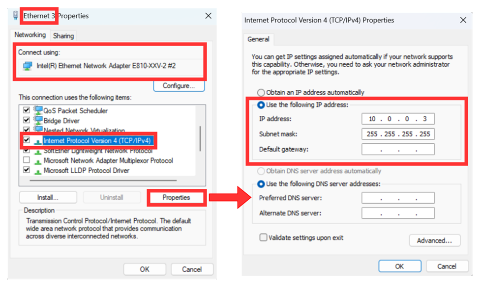
Figure 11 Setting IP address for PC
1) Open Local Area Connection Properties of 1 Gb connection, as shown in the left window of Figure 11.
2) Select “TCP/IPv4” and then click Properties.
3) Set IP address = 10.0.0.3 and Subnet mask = 255.255.255.0 as shown in the right window of Figure 11
4) Add a gateway IP route with highest priority matric using the command below:
> netsh interface ipv4 add route 10.0.0.0/24 "Ethernet 3" 10.0.0.1 metric=0
5) Open CMD as administrator and assign MAC address for gateway IP using the command below:
> netsh interface ipv4 add neighbor "Ethernet 3" 10.0.0.1 80-AB-CD-EF-12-AB
6.1.2 WireGuard Peer Configuration
Follow the steps in Section 3.2 to set up WireGuard software, using the configuration below:
[Interface]
PrivateKey = YKcfrhW7gOw47WJPEk1RobQPn+c9p0OURJYvZqvAz1g=
Address = 10.0.0.5/24
ListenPort = 51820
MTU = 8920
[Peer]
PublicKey = 2QqfRmehnyzkR5ZSeDkM7JUBNLo5CICdCQLxcBGOD0s=
PresharedKey = 4xZ9Lk2mQvR7wNpT3aBcYdHeJfUgXsOiK1nMqPlV8uE=
AllowedIPs = 10.0.0.3/32
6.1.3 WireGuard1G-IP Setup
On the Nios Command Shell, use all commands below to activate WireGuard1G-IP:
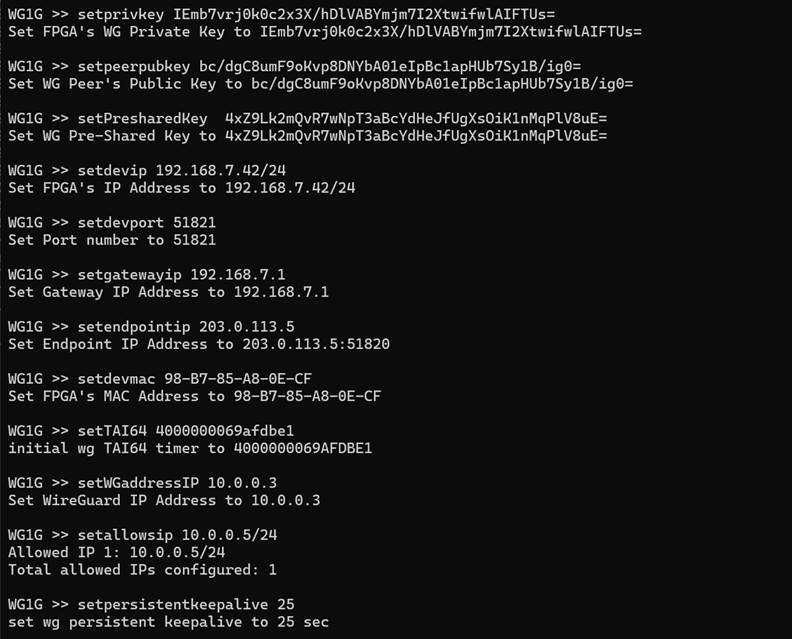
Figure 12 Example commands for WireGuard1G-IP on Nios Command Shell
6.1.4 Verify Connection
After completing the setup, the first WireGuard connection should be established. The WireGuard1G-IP status is displayed on the Nios Command Shell. Once data is transmitted or received through the tunnel, the transfer and receive sizes are continuously updated on the Nios Command Shell, as shown in Figure 13.
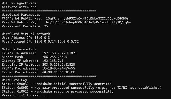
Figure 13 Activated WireGuard1G-IP Nios Command Shell
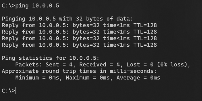
Figure 14 Verifying network connectivity using the ping command
6.2 Selective Encapsulation using GUI
The testing environment for the GUI demo is illustrated in Figure 15, consisting of three main components: the User PC, the FPGA board running the WireGuard1G-IP core, and the Endpoint PC.
The User PC connects directly to the FPGA over a 1 GbE link. Its single network interface is configured with two addresses. The local address 192.168.7.42 with gateway 192.168.7.1 is used for normal network traffic. The WireGuard tunnel address 10.0.0.3 with gateway 10.0.0.1 is used for traffic that should enter the tunnel. Since all WireGuard tunnel traffic is routed through the gateway, no manual ARP entries are required for individual WireGuard destinations.
The FPGA shares the same IP and MAC address as the User PC’s, allowing it to transparently intercept traffic. For outgoing packets sourced from the tunnel IP, it encapsulates and encrypts them into WireGuard packets before forwarding. For incoming packets, it decrypts and decapsulates them before delivering to the User PC.
On the other side, the Endpoint PC is reachable at 203.0.113.5 on the network and is assigned a WireGuard tunnel IP of 10.0.0.5. All encrypted WireGuard traffic is routed through the gateway to reach it.
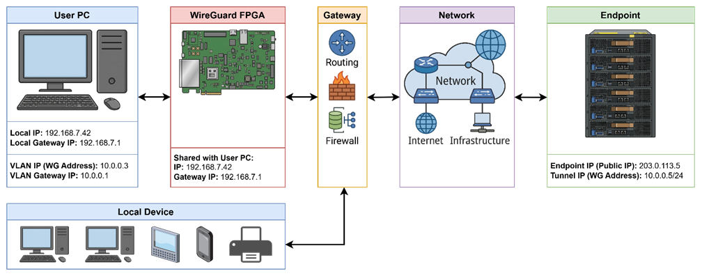
Figure 15 GUI testing environment
6.2.1 Graphical User Interface (GUI)
To simplify the use of the WireGuard1G IP core, a GUI application is provided as WireGuard-Demo-GUI.exe. The GUI allows users to configure the tunnel, connect to the FPGA via the JTAG-UART interface, activate or deactivate the WireGuard tunnel, and monitor real-time transfer statistics.
The GUI window is divided into two tabs: the Tunnel tab (for configuration and status monitoring) and the Log tab (for JTAG-UART console interaction). The main window is shown in Figure 16.
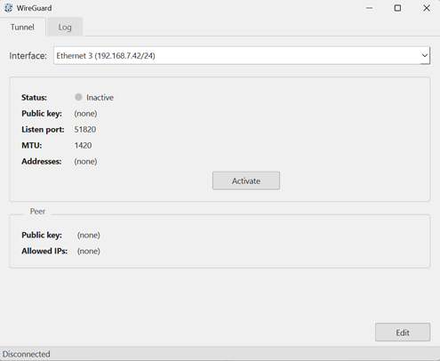
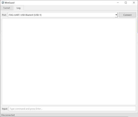
Figure 16 WireGuard Demo GUI window
Note: The WireGuard Demo GUI requires Administrator privileges to modify network interface settings (add IP addresses, configure routes, and manage the Kill Switch via Windows Filtering Platform).
6.2.2 Connect with FPGA device
To establish a connection with the FPGA:
1) Click the Port drop-down to see available JTAG-UART interfaces.
2) Select the JTAG-UART interface corresponding to the target FPGA device.
3) Click “Connect”. The status bar at the bottom left of the window will display “Connected” when the connection is established, as shown in Figure 17.
4) Once connected, the button label changes to “Disconnect”. Users can send manual commands via the Input field at the bottom of the Log tab.
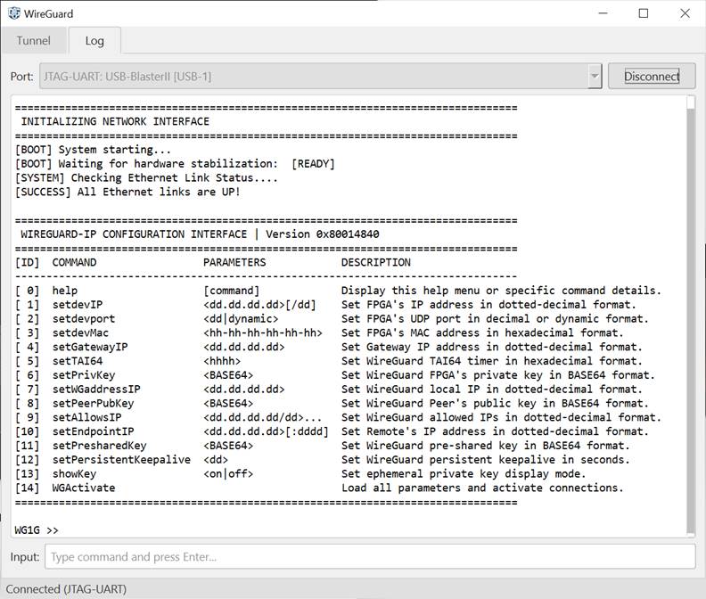
Figure 17 GUI log tab
6.2.3 User PC Setup
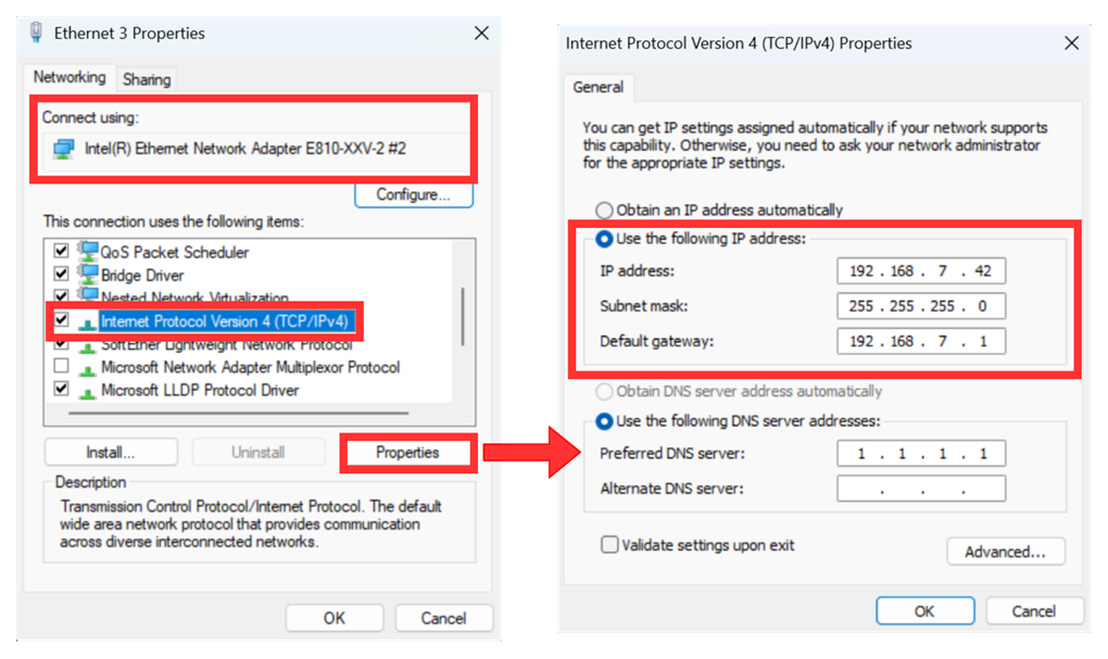
Figure 18 Setting IP address for PC
6) Open Local Area Connection Properties of 1 Gb connection, as shown in the left window of Figure 18.
7) Select “TCP/IPv4” and then click Properties.
8) Set IP address = 192.168.7.42, Subnet mask = 255.255.255.0 and Default gateway = 192.168.7.1 as shown in the right window of Figure 18
6.2.4 WireGuard Peer Configuration
Follow the steps in Section 3.2 to set up WireGuard software, using the configuration below:
[Interface]
PrivateKey = YKcfrhW7gOw47WJPEk1RobQPn+c9p0OURJYvZqvAz1g=
ListenPort = 51820
Address = 10.0.0.5/32, 10.90.1.6/32
MTU = 8920
[Peer]
PublicKey = 2QqfRmehnyzkR5ZSeDkM7JUBNLo5CICdCQLxcBGOD0s=
AllowedIPs = 10.0.0.3/32
6.2.5 Edit Tunnel Configuration
To configure the WireGuard tunnel parameters, click the “Edit” button on the Tunnel tab. The Edit Tunnel dialog will open, as shown in Figure 19.
· The Public key field at the top is read-only. It is automatically computed from the PrivateKey field.
· The configuration text editor accepts the standard WireGuard INI configuration format. The supported fields are described in Table 1.
· Click “Import” to load an existing WireGuard configuration file (.conf).
· Click “Save” to validate and save the configuration. The configuration is written to tun.conf in the application directory.
Table 1 Supported configuration fields
|
Field |
Section |
Description |
|
PrivateKey |
[Interface] |
FPGA’s X25519 private key (Base64, 44 chars). |
|
ListenPort |
[Interface] |
FPGA’s UDP listen port. Default: 51820. |
|
Address |
[Interface] |
WireGuard interface IP. |
|
MTU |
[Interface] |
Optional physical MTU (1–8920). Default: 1420. |
|
PublicKey |
[Peer] |
WireGuard peer’s public key (Base64, 44 chars). Required. |
|
AllowedIPs |
[Peer] |
Subnets routed through the tunnel in CIDR notation. Accepts up to 16 entries separated by space. Use 0.0.0.0/0 to route all traffic through the tunnel. |
|
Endpoint |
[Peer] |
Peer endpoint in IP:Port format. |
|
PersistentKeepalive |
[Peer] |
Optional keepalive interval in seconds (0 = disabled). Default: 0. |
|
PresharedKey |
[Peer] |
Optional symmetric preshared key (Base64, 44 chars). |
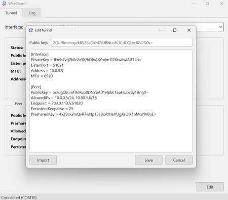
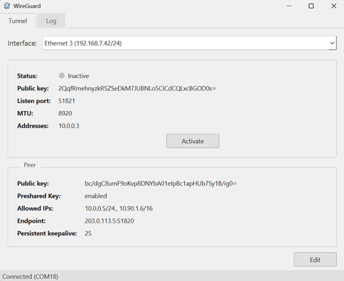
Figure 19 Parameters config
6.2.6 Activate Tunnel
When the user clicks “Activate”, the GUI automatically performs all configuration steps on both the FPGA (via the JTAG-UART port) and the User PC (via CLI). The following steps detail each action taken and the corresponding commands executed on the PC using the example configuration from Figure 19.
1) Resolve endpoint MAC address.
2) Set new MTU.
> netsh interface ipv4 set subinterface “Ethernet 3” mtu=8920 store=active
3) Add the tunnel IP address to the network adapter.
> netsh interface ipv4 add address “Ethernet 3” 10.0.0.3 255.255.255.255
4) Add routes for all Allowed IPs through the tunnel, using 10.0.0.1 as the next-hop (derived from the tunnel Address 10.0.0.3 by replacing the last octet with 1).
> netsh interface ipv4 add route 10.0.0.0/24 “Ethernet 3” 10.0.0.1 metric=0
> netsh interface ipv4 add route 10.90.0.0/16 “Ethernet 3” 10.0.0.1 metric=0
5) Assign endpoint MAC address to next-hop IP.
> netsh interface ipv4 add neighbor “Ethernet 3” 10.0.0.1 98-B7-85-A8-0E-CE
6) Send configuration commands set from Figure 19 to the FPGA via Nios Command Shell.
7) Send the “WGActivate” command to the FPGA to apply all parameters and initiate the handshake. The log Nios Command Shell will enter monitor mode and print status codes and transfer statistics.
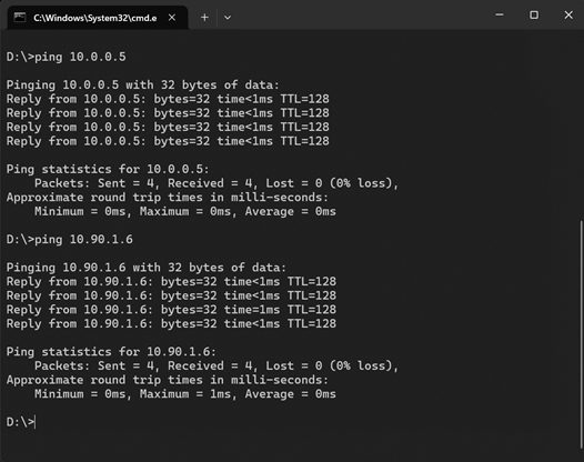
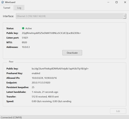
Figure 20 WireGuard tunnel activated
When the tunnel is active, the Tunnel tab in the GUI displays the following live statistics:
· Latest handshake: time elapsed since the last successful WireGuard handshake.
· Transfer: cumulative bytes received and sent through the tunnel.
· Speed: current receive and transmit speeds in Gb/s
To verify functional connectivity through the tunnel, users can use standard network tools such as ping (e.g., ping 10.0.0.5) to confirm end-to-end reachability, or any application that generates traffic over the tunnel IP.
6.2.7 Deactivate Tunnel
When the user clicks “Deactivate”, the GUI reverses all configuration steps applied during activation in Section 6.2.6. The following steps detail each action taken and the corresponding commands executed on the PC.
1) Send “Ctrl + X” to the FPGA via Nios Command Shell to terminate the WireGuard session.
2) Restore the original MTU of the network adapter.
> netsh interface ipv4 set subinterface “Ethernet 3” mtu=9000 store=active
3) Remove the tunnel IP address from the network adapter.
> netsh interface ipv4 delete address “Ethernet 3” 10.0.0.3
4) Remove the routes added for all Allowed IPs.
> netsh interface ipv4 delete route 10.0.0.0/24 “Ethernet 3” 10.0.0.1
> netsh interface ipv4 delete route 10.90.0.0/16 “Ethernet 3” 10.0.0.1
5) Remove the endpoint ARP neighbor entry.
> netsh interface ipv4 delete neighbor “Ethernet 3” 10.0.0.1
6) Once deactivated status is received from Nios Command Shell, the Tunnel tab returns to its inactive state and the live statistics are cleared from the display.
7 Performance Test
This section evaluates the throughput performance of the WireGuard1G-IP core using iperf3. The objective of this test is to verify that the hardware implementation can sustain the full bandwidth of a 1 Gbps Ethernet link while processing WireGuard traffic.
7.1 PC to PC via WireGuard1G-IP
In this scenario, the environment described in Section 6.2. is used
On the Endpoint PC, run:
iperf3 -s
On the User PC, run:
iperf3 -c 10.0.0.5 --bidir -w 1MB
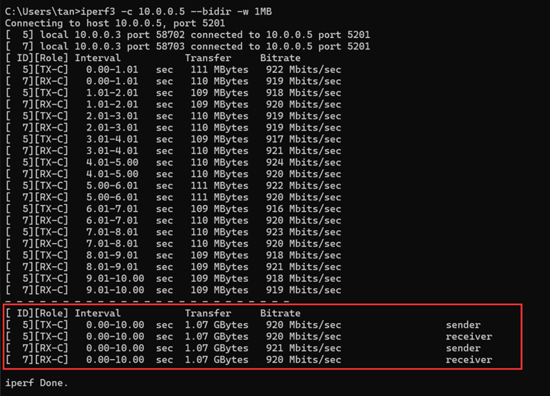
Figure 21 WireGuard1G-IP iperf3 result
7.2 Result Summary
As shown in Figure 21, the WireGuard1G-IP core successfully sustains bidirectional encrypted traffic at the full 1 Gbps Ethernet line rate. The result confirms that the hardware implementation can process WireGuard traffic without introducing a throughput bottleneck, fully utilizing the available network bandwidth.
8 Revision History
|
Revision |
Date (D-M-Y) |
Description |
|
1.00 |
29-Jul-26 |
Initial version release |