tCAM IP Demo Instruction on KCU116 board
Rev1.00 31-Aug-2023
4 Integrated Logic Analyzer (ILA) setup
4.1.1 To see Rule Initial Control signals
4.1.2 To see Rule Memory Interface signals
4.1.3 To see Input key and Search result signals
5.1 Demo software interface description
5.2 File format for Rule data and Key Data
5.5 Initialization rule data to FPGA Development board
This document describes the instruction to demonstrate the operation of tCAMIP on KCU116 development board. This demonstration uses tCAMIP demo software to communicate with development board via 10 Gigabit Ethernet for preparing rule table, initializing tCAMIP, sending keys and reading result data. User is also able to use Integrated Logic Ananlyzer (ILA) to see the operation of provided signals in FPGA.
1 Environment Setup
To operate tCAMIP demo, please prepare following test environment.
1) FPGA development boards (KCU116 development board)
2) Test PC with 10 Gigabit Ethernet card.
3) Micro USB cable for JTAG connection between FPGA development board and Test PC
4) 10Gb Ethernet cable (SFP+ to SFP+).
5) Vivado Hardware Manager for programming FPGA, installed on Test PC
6) File “tCAMIPDemoPack-KCU116.zip” that included Test Application named “tCAMIP Demo” and configuration file named “tCAMIPTest+.bit”.
(To download this file, please visit our web site at www.design-gateway.com)
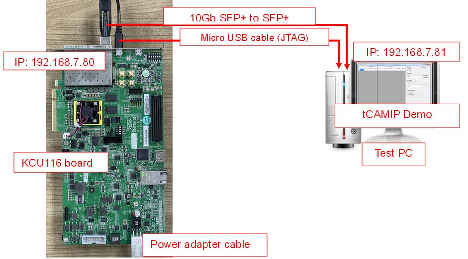
Figure 1‑1 tCAMIP demo on KCU116 board
2 PC Setup
Before running demo, please check the network setting on PC. Ethernet setting is shown as follows.
2.1 IP Setting
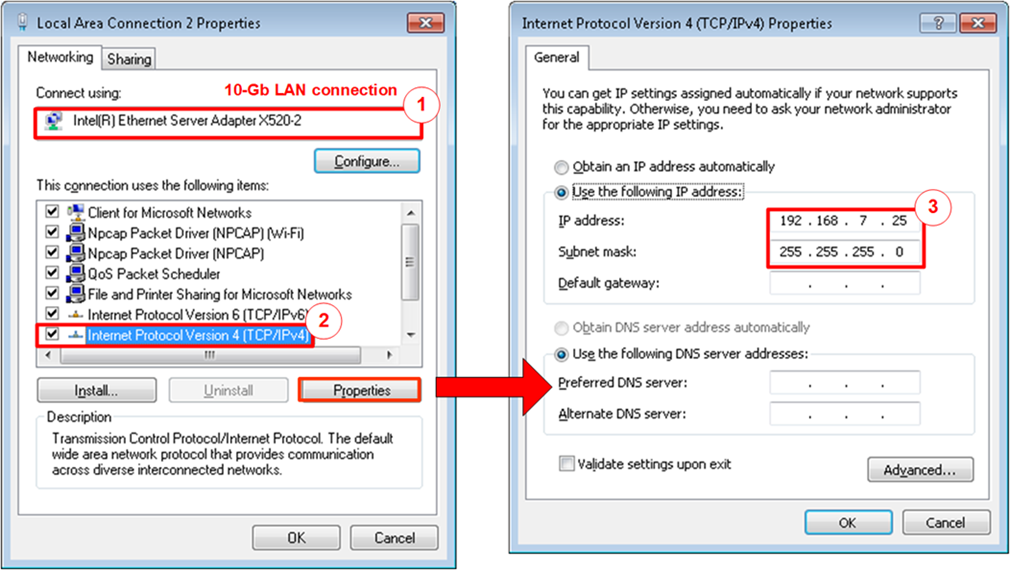
Figure 2‑1 Setting IP address for PC
1) Open Local Area Connection Properties of 10Gb connection, as shown in the left window of Figure 2‑1.
2) Select “TCP/IPv4” and then click Properties.
3) Set IP address = 192.168.7.81 and Subnet mask = 255.255.255.0, as shown in the right window of Figure 2‑1.
2.2 Speed and Frame Setting
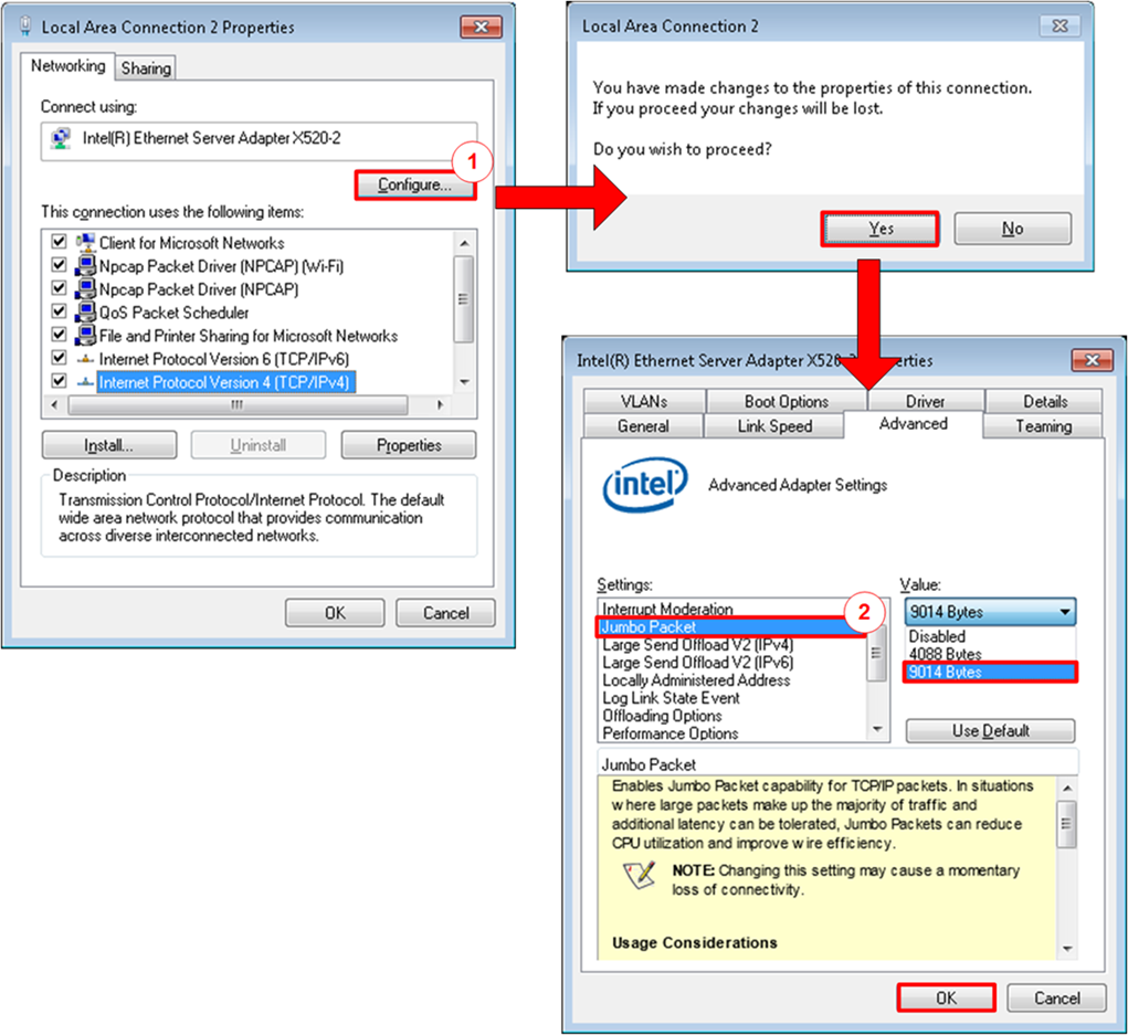
Figure 2‑2 Set frame size = jumbo frame
1) On Local Area Connection Properties window, click “Configure” as shown in Figure 2‑2.
2) On Advanced Tab, select “Jumbo Packet”. Set Value to “9014 Bytes” for Jumbo Frame support or set value to “Disabled” for non-Jumbo Frame support, as shown in the bottom window of Figure 2‑2.
3) On Link Speed, select “10 Gbps Full Duplex” for running 10-Gigabit transfer test, as shown in Figure 2‑3.
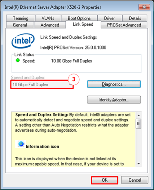
Figure 2‑3 Set link speed = 10 Gbps
4) On PROSet Advanced Tab, select “Performance Options” and click “Properties” button.
5) Set “Interrupt Moderation Rate” = OFF.
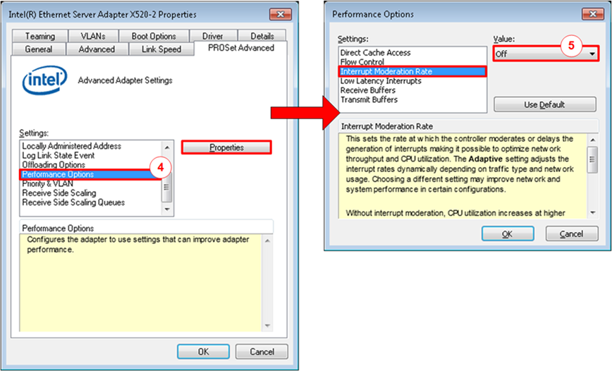
Figure 2‑4 Interrupt Moderation Rate
6) Select “Low Latency Interrupts” and click “Properties” button.
7) On “Low Latency Interrupts” window, select “Use Low Latency Interrupts” and click “OK” button.
8) Click “OK” button to save and exit all setting windows.
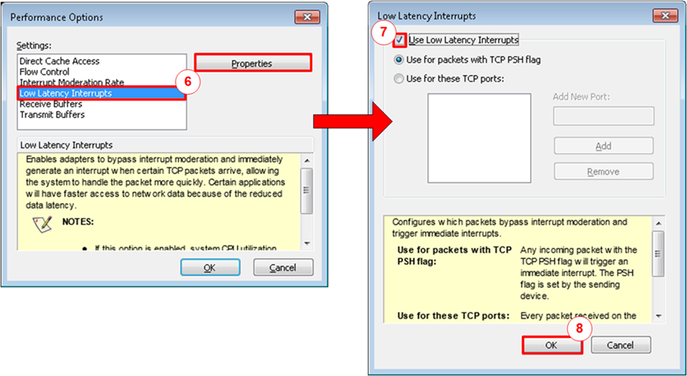
Figure 2‑5 Use Low Latency Interrupts
2.3 Power Option Setting
1) Open Control Panel and select Power Options as shown in the left window of Figure 2‑6.
2) Change setting to High Performance as shown in the right window of Figure 2‑6.
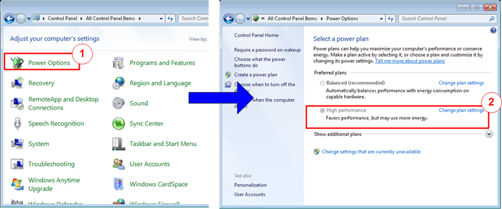
Figure 2‑6 Power options
3 FPGA board setup
1) Make sure power switch is off and connect power supply to KCU116 development board.
2) Connect 10Gb SFP+ cable from KCU116 board to PC.
3) Connect USB cable between PC to JTAG micro USB port.
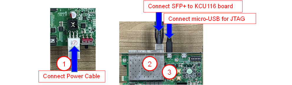
Figure 3‑1 Power, Ethernet, and micro-USB cable connection for KCU116 board
4) Power on system.
5) Open Vivado Hardware Manager to program FPGA by following step.
a) Click “Auto Connect” to connect with board.
b) Right Click at “xcku5p_0”, then select “Program device …”
c) Select “.bit” for configuration bit file.
d) Select “.ltx” for debug probe file.
e) Press “Program” button to program device.
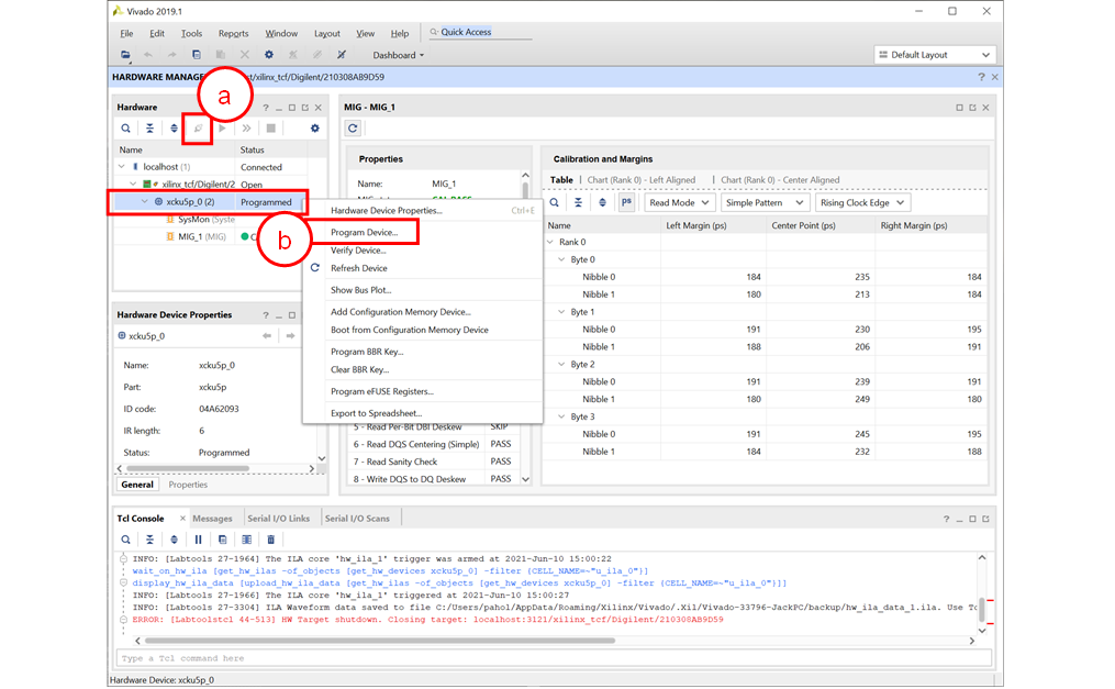
Figure 3‑2 Vivado Hardware Manager
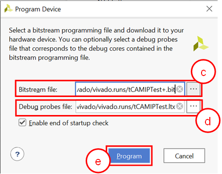
Figure 3‑3 Program Device
6) When configuration is completed, user can check status LEDs on board as Figure 3‑4.
o LED0 is “Busy” status of TOE10G-IP. This LED is on when ethernet connection between PC and board is busy, user can re-check connection cable and all ethernet setting again.
o LED1 is “Connection on” status of TOE10G-IP. This LED is on when software open connection to board successfully.
o LED2 is show reset status.
o LED3 is always blink to show clock is working.
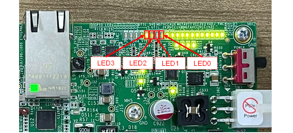
Figure 3‑4 LED[3:0] status on board
4 Integrated Logic Analyzer (ILA) setup
This designed block diagram of this demo is shown as in Figure 4‑1. ILA is prepared to see all control signals between tCAMIP and user logics design.
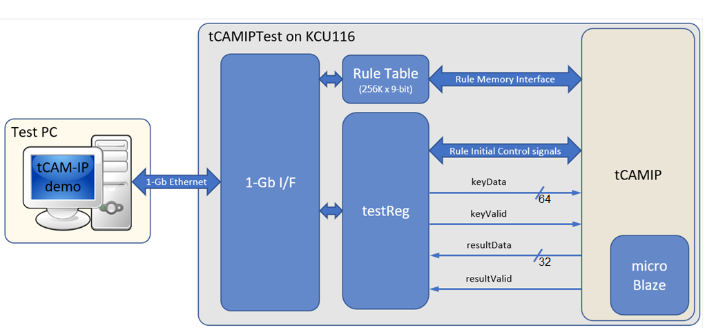
Figure 4‑1 Demo environment block diagram
4.1 ILA trigger condition
On demo running, user is able to use ILA to setup trigger condition and check the signal waveform after trigger is detected. The prepared ILA signals are separated to 3 parts as (1) Rule Initial control signals, (2) Rule Memory interface signals and (3) Input keys & search result signal respectively.
4.1.1 To see Rule Initial Control signals
Figure 4‑2 show trigger condition and Figure 4‑3 show sample result from ILA when user do initial rule table in topic 5.5
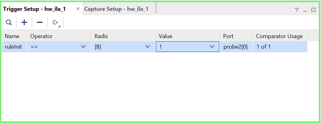
Figure 4‑2 Trigger setup for rule initial control signals
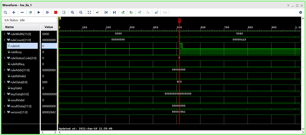
Figure 4‑3 Sample result for rule initial control signals
4.1.2 To see Rule Memory Interface signals
Figure 4‑4 show trigger condition and Figure 4‑5 show sample result from ILA when user do initial rule table in topic 5.5
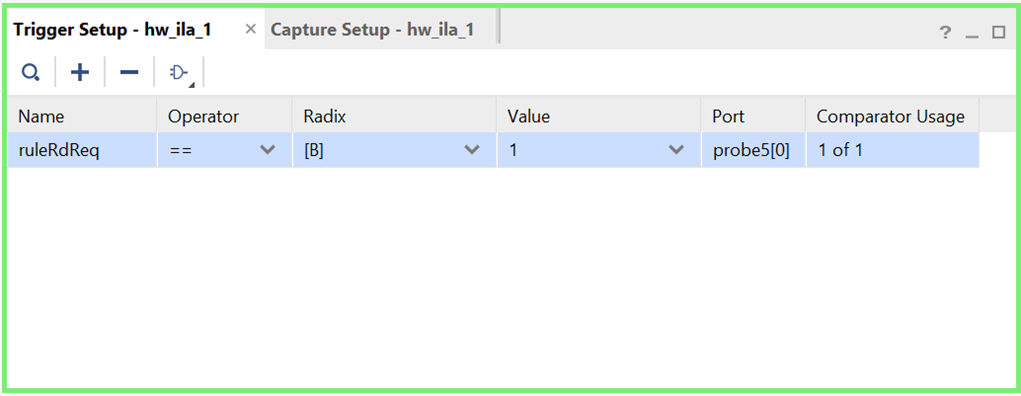
Figure 4‑4 Trigger setup for rule memory signals
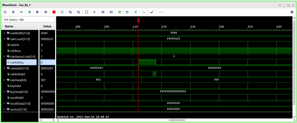
Figure 4‑5 Sample result for rule memory signals
4.1.3 To see Input key and Search result signals
Figure 4‑6 show trigger condition and Figure 4‑7 show sample result from ILA when user do initial rule table in topic 5.6
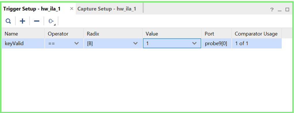
Figure 4‑6 Trigger setup for input key and searching result
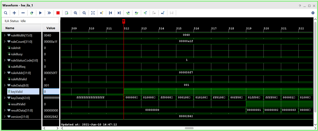
Figure 4‑7 Sample result for input key and searching result
5 tCAMIP demo software
tCAMIP demo software is used for preparing and sending rule and key pattern data to KCU116 board via 10 Gigabit Ethernet connection and getting the result of searching from tCAMIP.
The main features of tCAMIP demo software are as following.
2) Key creation.
3) Initialization rule data table to FPGA development board.
4) Search key data and display result.
5) Compare expect data of key data searching to result data of key data searching.
5.1 Demo software interface description
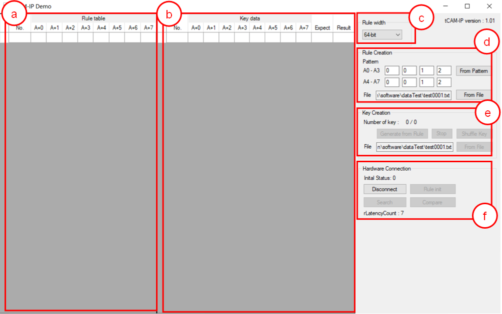
Figure 5‑1 Software interface
Figure 5‑1 shows tCAMIP demo software and the description is shown as below.
a) Rule table is the user rule data display.
b) Key data table is the user key data display.
c) Rule width, Users can select data size modes.
d) Rule Creation, Users can generate rule data table pattern or load rule data table pattern from the file.
e) Key Creation, Users can generate key data from rule table or load key data table pattern from the file.
f) Hardware Connection, Users can communicate with FPGA development board in this part. Which consists of connection with board, rule Initialize, key data search, result compare.
5.2 File format for Rule data and Key Data
User can prepare Rule data or Key data file for this demo. The file format is shown as Figure 5‑2 and Figure 5‑3 for rule width 32-bit and 64-bit respectively.
1) The first line is header of file for specific number of byte data in this file like “A+0, A+1, A+2, A+3” for 32-bit file format.
2) Next lines are data. The valid range of data is 0-255, others number and ‘x’ is defined to don’t care value.
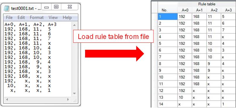
Figure 5‑2 Example of load rule file 32-bit
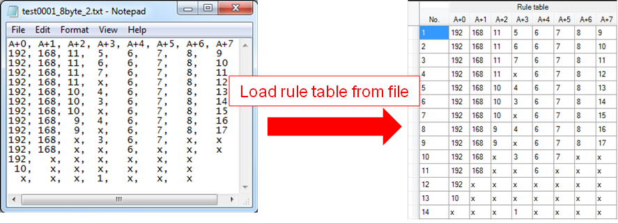
Figure 5‑3 Example of load rule file 64-bit
5.3 Rule table creation
To create the rule table, the step is shown as in Figure 5‑4.
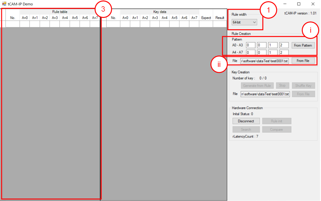
Figure 5‑4 Rule creation process
1) Select Rule width mode for setup data size.
2) Create rule table, the user can select 2 modes as follows.
i) Generate rule data table from pattern as show in Figure 5‑5.
a) Fill out valid range (0-256) of each byte in “Pattern”. Byte of pattern position starts “A+0” left to right.
b) Click “From Pattern” to start generate rule table.
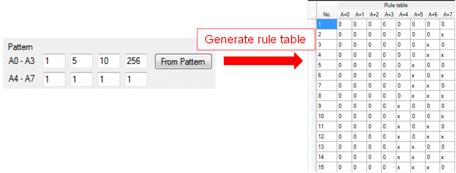
Figure 5‑5 Example rule data table pattern.
ii) Load rule data table from the file by click “From File” button to browse and load rule data file.
3) When rule is created, rule data show in rule table as shown in Figure 5‑4.
5.4 Key data table creation
To create key table, the step is shown as in Figure 5‑6.
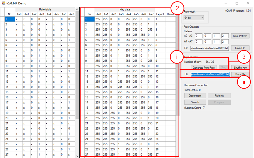
Figure 5‑6 Key creation
1) Create Key data, the user can select 2 modes as follows
i) Generate key data from rule table.
a) Click “Generate from Rule” to start generate all possible key data from rule table.
b) “Number of key: X / Y” is progress status by X is progress number of key and Y is total number of keys from all combination of rules. (generating time depends on the amount of key data)
c) “Stop” button is used for stop key generating.
ii) Load key data from the file by click “From File” button to browse and load rule data file.
2) When key data is created, the expect value will be generated automatically.
3) “Shuffle Key” button is used to shuffle each key in key table randomly.
5.5 Initialization rule data to FPGA Development board
The step to initialize rule data is following as below and Figure 5‑7.
1) Please make sure that LED0 (TOE10G busy) is off (please refer LEDs on board in Figure 3‑4), before click “Connect” button.
2) When connection is completed, the text of the button will change to “Disconnect” and LED1 (open connection status) is turn on. The button “Rule init”, “Search” button will be enabled.
3) On Vivado Hardware Manager, setup trigger condition when ruleInit = ’1’ and other signals are don’t care. Then press “Run trigger” button.
4) Click “Rule init” button to initialize data of rule table. Initialization duration time depends on the amount of key data.
According to ruleTable size is 256K x 9-bit. If rule data is more than ruleTable size, the verify error may be shown when rule data is written overflow.
“Initial Status: X” is active status for Rule transfer, Rule verify, Rule initial and Status code. By X is running number of rule table, time count of Rule initial status and status code which shows that process is still running.
· When ruleInit signal = ‘1’, Vivado Hardware Manger will show all interface signals of tCAMIP.
· In case to see the difference trigger point, user can change trigger condition in Vivado Hardware Manger on step 3).
5) When initialization is completed, the message box will popup “Rule initial completed”.
In case initialization is incomplete, “Initial Status:” is shown error message of status code.
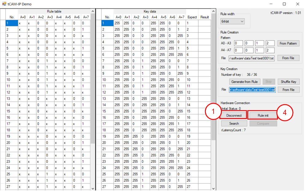
Figure 5‑7 Rule initialization
5.6 Searching key data
To search key data by the hardware of tCAMIP demo, the step is following as below and Figure 5‑8.
1) On Vivado Hardware Manger, setup trigger condition when keyValid = ’1’ and other signals are don’t care. Then press “Run trigger” button.
2) Click “Search” button to run key data searching.
3) When search is completed, the message box will popup “Search completed”
· Vivado Hardware Manger will show all signals interface of tCAMIP as shown in Figure 5‑9
· In case to see the different trigger point, user can change trigger condition in Vivado Hardware Manger on step 1).
4) Result of key search will be displayed to ‘Result’ column. “rLantencyCount: X” show number of clocks between first key data to first result data.
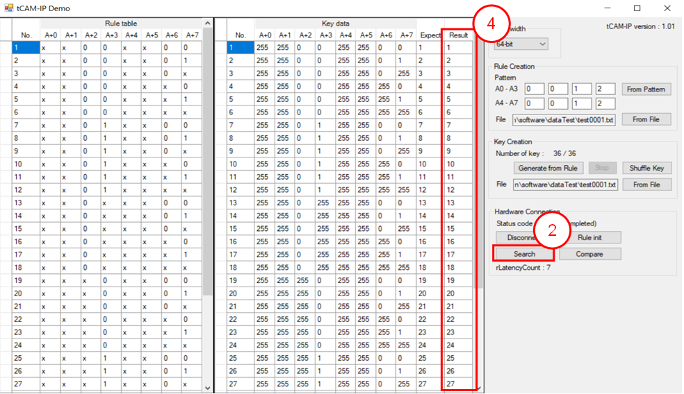
Figure 5‑8 Search key data
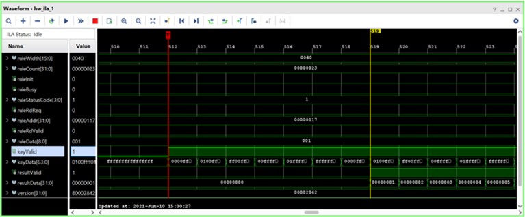
Figure 5‑9 Sample of ILA result
5.7 Compare
To compare between the expected value (from software) and result from hardware searching, the step is as shown in Figure 5‑10.
1) Click “Compare” button to compare expect data and result data of key data.
2) When comparing is completed, if compare have mismatch. The message box will popup “Completed with X mismatch found”, By X is number of mismatches found.
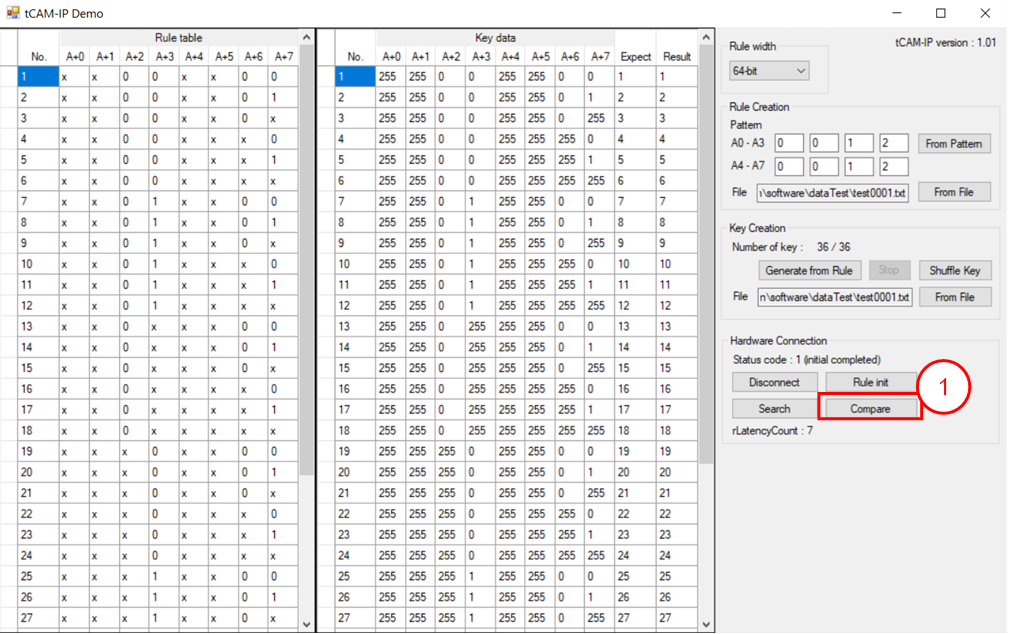
Figure 5‑10 Step to compare data.
6 Revision History
|
Revision |
Date |
Description |
|
1.00 |
30-Jun-2021 |
Initial version release
|