
Core Facts |
|
|
Provided with Core |
|
|
Documentation |
User Guide, Design Guide |
|
Design File Formats |
Encrypted File |
|
Instantiation Templates |
VHDL |
|
Reference Designs & Application Notes |
Quartus Project, See Reference Design Manual |
|
Additional Items |
Demo on A10SoC, Agilex7 I-Series development kit |
|
Support |
|
|
Support Provided by Design Gateway Co., Ltd. |
|
Design Gateway Co.,Ltd
E-mail: ip-sales@design-gateway.com
URL: design-gateway.com
Features
· Key width 64/56/48/40/32/24 bits
· Up to 1M rule entries
· Searching latency is constant at 7 clock cycles
· Up to 400 MSPS @ 400MHz searching speed.
· Easy to customize rule table memory
· Simple rule table memory setup and user interface signals
Customizable
· Extend max rule width bits
· Extend max rule entries
· To support external memory
Table 1: Example Implementation Statistics for tCAMIP 64-bit up to 1M rule entries
|
Family |
Example Device |
Fmax (MHz) |
ALMs |
Registers1 |
M20Ks2 |
Design Tools |
|
Agilex7 I-Series |
AGIB027R29A1E2VR3 |
400 |
8,390.1 |
9,060 |
1,101 |
Quartus 23.1 |
|
Arria10 SX |
10AS066N3F40E2SGE2 |
200 |
3,042.5 |
2,710 |
1,328 |
QuartusII 16.0 |
Table 2: Example Implementation Statistics for tCAMIP 32-bit up to 512K rule entries
|
Family |
Example Device |
Fmax (MHz) |
ALMs |
Registers1 |
M20Ks2 |
Design Tools |
|
Arria10 SX |
10AS066N3F40E2SGE2 |
200 |
1,782 |
2,219 |
652 |
QuartusII 16.0 |
Notes:
(1) Actual logic resource dependent on percentage of unrelated logic.
(2) Exclude user rule table memory, Ex: 512K x 9-bit rule table memory will take 288 M20Ks.
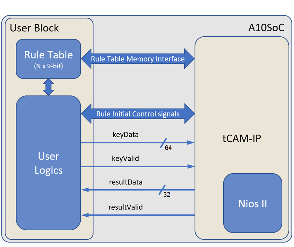
Figure 1: tCAMIP Block Diagram
Applications
tCAMIP is content addessable memory based on FPGA, that provide extremely low latency matching function at 200MSPS (million samples per second) continuously matching speed. It can achieve 200 M-Packet/sec (million packets per second) filtering on 100Gbps ethernet.
General Description
tCAMIP is required simple process initialization that is described in the next topics. After tCAMIP analyze rule data table and initialize internal matching logics. When initialize process is completed, tCAMIP can continuously pass key to searching @ 200MSPS, and send matching result with fixed 7 clock cycles latency from key.
Functional Description
tCAMIP core can be divided into three parts, i.e. rule table memory interface signals, rule initialize control signals, and key searching signals.
Table 2: Interface signals of tCAMIP
|
Signal name |
Dir |
Description |
|
RstB |
In |
IP core system reset. Active low. |
|
Clk |
In |
IP core system clock. |
|
Rule table memory interface signals |
||
|
ruleAddr[31:0] |
Out |
ruleAddr is 32-bit address signal, that tCAMIP send to memory in first clock of read cycle. And hold value until get ruleRdValid='1' from memory module. |
|
ruleRdReq |
Out |
ruleRdReq is request signal, that tCAMIP send logic '1' to memory in first clock of read cycle. And hold '1' until get ruleRdValid='1' from memory module. |
|
ruleRdValid |
In |
ruleRdValid is data valid signal, that memory module set to '1', one clock when ruleData is valid. |
|
ruleData[8:0] |
In |
ruleData is read data signal, that memory module return data in memory to tCAMIP |
|
Rule initializes control signals |
||
|
ruleWidth[15:0] |
In |
ruleWidth is 16-bit value to specify number bits of rule. tCAMIP can support 64/56/48/40/32/24-bit width. |
|
ruleCount[31:0] |
In |
ruleCount is 32-bit value to specify number of rules to initialize tCAMIP for searching. |
|
ruleInit |
In |
ruleInit is request signal send to tCAMIP for start initialize process. tCAMIP will keep ruleWidth and ruleCount value in the first clock of ruleInit='1' and use for initialize process. |
|
ruleBusy |
Out |
ruleBusy is set to '1' when tCAMIP detected ruleInit='1', and ruleBusy is hold to be '1' until initialize process is finished, then tCAMIP will pull ruleBusy to be '0'. |
|
ruleStatusCode[3:0] |
Out |
ruleStatusCode is shown initialize status of tCAMIP. User can read this signal when initialize process is finished (ruleBusy change from '1' to '0') |
|
Key searching signals |
||
|
keyValid |
In |
keyValid is user signal to specify data valid of keyData |
|
keyData[63:0] |
In |
keyData is 64-bit key data of searching. tCAMIP can continuously search every clock cycle. |
|
resultValid |
Out |
resultValid specify data valid for resultData, tCAMIP generate resultValid signal from keyValid with 7 clock cycles latency |
|
resultData[31:0] |
Out |
resultData is 32-bit result data of searching key. resuleData has fixed latency at 7 clock cycles latency from keyData |
· Rule Table memory interace
tCAMIP is designed to separate rule table memory that is more flexible to customize by user. User may use simple memory IP generate by Quartus software, or use external memory like SD-RAM, DDR-RAM, etc.
Rule table memory interface signals is simple memory interface. Figure 2 shows timing diagram of rule table memory interface signals, user can simple customize memory latency time by delay ruleRdValid signal.
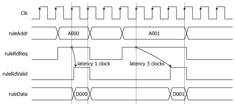
Figure 2: Rule Table memory interface timing diagram
· Rule Table memory initialize value
Rule Table memory is designed based on 9-bit data width memory, because rule value range is 0 to 255 and 256 for don’t care.
The first step of initialize process, user need to set all value in the rule table memory before send rule initialize control signals. Figure 3 shows example of memory address mapping from user rule data for 64-bit width of rule. The maximum memory require 8192K x 9-bit for maximum 1024K rules combination.
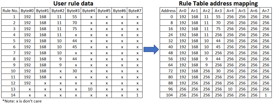
Figure 3: Example of Rule Table initialize values for 64-bit width of rule
Figure 4 shows example of memory address mapping from user rule data for 32-bit width of rule. The maximum memory require 4096K x 9-bit for maximum 1024K rules combination.
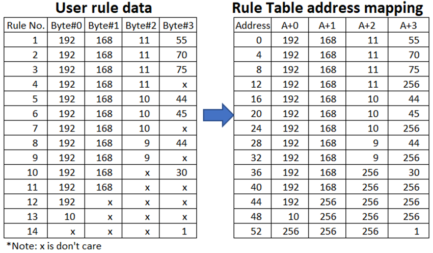
Figure 4: Example of Rule Table initialize values for 32-bit width of rule
Figure 5 shows example of memory address mapping for 24-bit width of rule. The maximum memory require 1536K x 9-bit for maximum 512K rules combination.
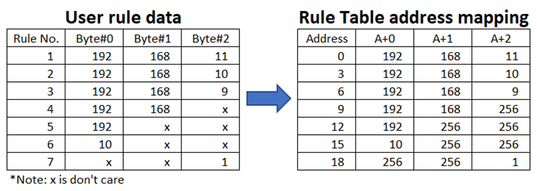
Figure 5: Example of Rule Table initialize values for 24-bit keys
Priority of searching process is based on ascending sequence of rules in rule table memory. For more understanding about priority, examples of searching key and result based on Figure 4 is shown as below.
o When searching key is 192.168.10.30, the result is rule no. 7
o When searching key is 192.168.20.30, the result is rule no. 10
o When searching key is 192.100.10.30, the result is rule no. 12
o When searching key is 111.111.111.111, the result is rule no. 0 (0 is default value of rule x.x.x.x)
· Rule Initialize control signals
User can specify ruleWidth as number bits of each rule (64/56/48/40/32/24), ruleCount as number of rules. Then set ruleInit signal to ‘1’. The tCAMIP will acknowledge ruleInit signal by set ruleBusy to be ‘1’. The tCAMIP will take some times to analyze prepare internal matching parameter, initialized time is up to ruleWidth and ruleCount values. When initialize process is finished, tCAMIP will set ruleStatusCode before pull ruleBusy signal to be ‘0’ as shown in Figure 6
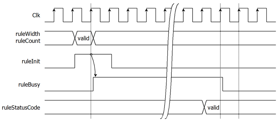
Figure 6: Rule initialize control signals timing diagram
ruleStatusCode meaning is shown as below.
0 : no initialize yet. (after power or hardware reset state)
1 : initialize completed.
2 : error with ruleCount is over maximum number of rules.
3 : error with rule value patterns are generated over maximum number of CAM.
When user detect ruleStatusCode is 2 or 3, tCAMIP is not ready for searching. User can retry initialize again by change ruleWidth, ruleCount and set ruleInit to ‘1’ for restart initialize process again.
After initialize process is finished with ruleStatusCode = 1, tCAMIP can continuously search key every clock cycle by result has fixed latency at 7 clock cycles.
· Key searching signals
After rule initialize process is completed, user can continuously send key to search in tCAMIP. resultValid signal is provided to easy control signal for matching between key and result as shown in Figure 7
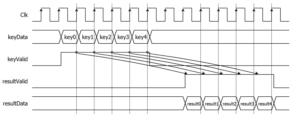
Figure 7: Key searching signals timing diagram
Example usage
The example sequence to initial tCAMIP is shown as Figure 8
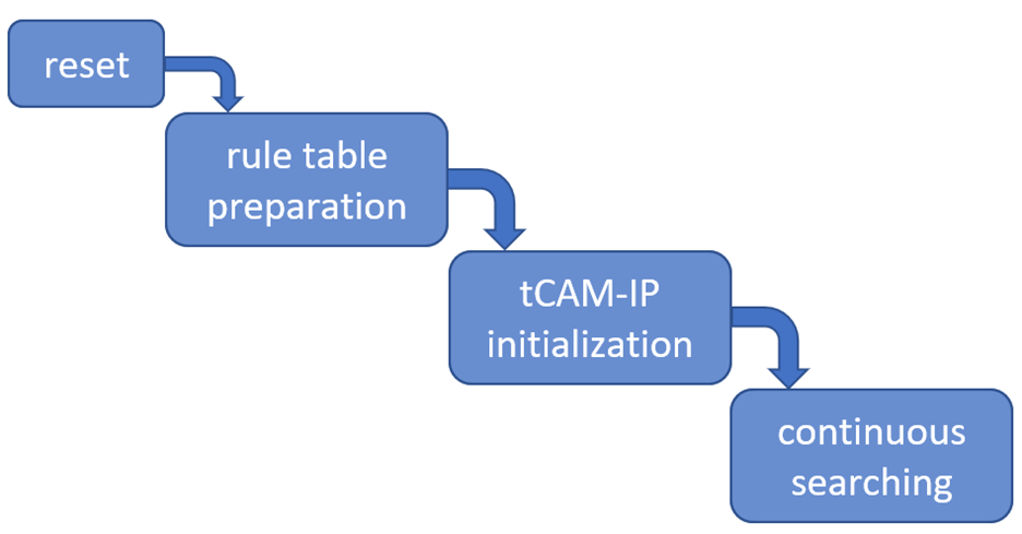
Figure 8: User operation flow
1) User can reset tCAMIP by set RstB = ‘0’
2) User prepare all rule values in rule table memory
3) User start initial tCAMIP by …
a. set ruleInit = ‘1’ while ruleWidth and ruleCount are valid values, wait until ruleBusy = ‘1’, then pull ruleInit = ‘0’
b. wait until ruleBusy = ‘0’, and check ruleStatusCode. If ruleStatusCode is not “1”, redo from Step 2)
4) User can continuously send key to search, and result will come out with 7 clock cycles latency.
Limitation
- Maximum number of rules is up to rule pattern optimization. In the most of patterns, tCAMIP can fit less than 1M rules.
Verification Methods
The tCAMIP Core functionality was verified on real board design by using Arria10 SoC and Agilex-I development board.
Recommended Design Experience
User must be familiar with HDL design methodology to integrate this IP into system.
Ordering Information
This product is available directly from Design Gateway Co., Ltd. Please contact Design Gatway Co., Ltd. For pricing and additional information about this product using the contact information on the front page of this datasheet.
Revision History
|
Revision |
Date |
Description |
|
1.03 |
21/Jul/2023 |
Add Agilex7 I-Series |
|
1.02 |
4/Mar/2021 |
Revise |
|
1.01 |
25/Aug/2020 |
- Support up to 64-bit width of rule. - Bit code utilization improvement. |
|
1.00 |
4/Jun/2020 |
New release |