FTP 25G Server FPGA Setup
Rev1.0 3-Jul-23
This document describes how to setup FPGA board and prepare the test environment for running FTP 25G Server demo on FPGA development board by using FileZilla version 3.45.1 as FTP client. NVMe SSD is applied as the storage for storing file transferred with TestPC by using FTP protocol via 25Gb Ethernet. User sets the test parameters on FPGA and monitors the hardware status via Serial console.
1 Environment Requirement
To run FTP Server demo, please prepare following test environment.
1) FPGA development board: KCU116
2) Test PC with 25 Gigabit Ethernet card and installed program as follows:
· Vivado tool for program the FPGA
· FileZilla version 3.45.1 to be test application
· Serial console software such as HyperTerminal or TeraTerm. The setting on the console is Baudrate=115,200, Data=8-bit, Non-parity, and Stop=1.
3) 25 Gb Ethernet cable: 25G SFP28 Active Optical Cable (AOC)
4) The PCIe adapter board (AB18-PCIeX16 or AB16-PCIeXOVR) provided by Design Gateway
https://dgway.com/ABseries_E.html
5) NVMe SSD connecting to PCIe adapter board
6) Two micro USB cables connecting between FPGA board and PC (one for programming FPGA and another for Serial console)
7) Xilinx power adapter for FPGA board
8) ATX power supply for AB18-PCIeX16 or AB16-PCIeXOVR adapter board
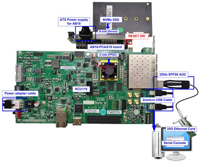
Figure 1‑1 FTP Server demo on KCU116 with AB18
2 FPGA board setup
1) Power off system.
2) Setup and connect NVMe SSD to PCIe adapter board.
For KCU116, connect to AB18-PCIeX16 and AB16-PCIeXOVR.
a) Confirm that two mini jumpers are inserted at J5 connector on AB18.
b) Connect ATX power supply to AB board.
c) Connect PCIe connector on FPGA board to FPGA Side (A-side) and connect NVMe PCIe SSD to device side (B-Side) on AB board, as shown in Figure 2‑1.
Caution: Please confirm that the SSD is inserted in the correct side of AB18 (B-side, not A-side) before power on system
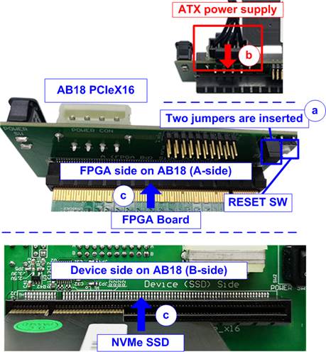
Figure 2‑1 Connect AB18-PCIeX16 to KCU116
3) Connect 25Gb Ethernet cable by inserting 25G SFP28 AOC cable between FPGA board (on the left-most channel) and 25Gb Ethernet card on Test PC, as shown in Figure 2‑2.

Figure 2‑2 Connect SFP28 channel using on KCU116 board
4) Connect two micro USB cables from FPGA board to PC for JTAG programming and Serial console.
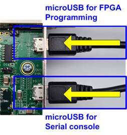
Figure 2‑3 micro USB connection of FPGA
5) Power on FPGA development board and adapter board, as shown in Figure 2‑4.

Figure 2‑4 Turn on power switch on FPGA and adapter board
6) Open Serial console. When connecting FPGA board to PC, many COM ports from FPGA connection are detected and displayed on Device Manager.
In case of KCU116, select Standard COM port.
On Serial console, use following setting: Buad rate=115,200, Data=8-bit, Non-Parity and Stop = 1.
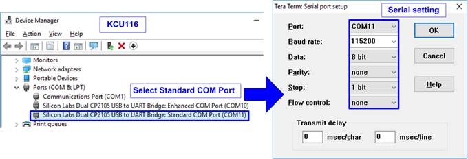
Figure 2‑5 Select and set COM Port
7) Set Clock of Si570 on KCU116 to 322.265625 MHz by using “KCU116 – Board User Interface” application.

Figure 2‑6 SCUI of KCU116
8) Download configuration file and firmware to FPGA board
For KCU116, configure FPGA by using Vivado, as shown in Figure 2‑7.
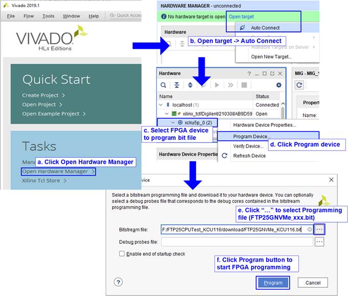
Figure 2‑7 Program FPGA by using Vivado
3 Revision History
|
Revision |
Date |
Description |
|
1.0 |
14-Oct-20 |
Initial version release |