FTP Server by muNVMe-IPG4 Reference Design Manual
1.1.1 FTP Connection Establishment and User Authentication
1.1.2 FTP Data Connection Management by Passive Mode
1.2 FPGA-Based FTP Server for Two-User Access
2.1 100G Ethernet MAC Subsystem (100G BASE-SR)
3.1 FTP Command and Response Handler
3.3.3 Change Time Created by FTP
3.3.4 Print Progress (FTP/exFAT)
3.4.1 FTP Commands without Data Connection
3.4.2 FTP Command with Data Connection
3.5 Function list in Test firmware
3.5.3 Function for FTP operation
1 Overview
1.1 FTP Introduction
File Transfer Protocol (FTP) is a standard network protocol used for file transmission between a client and server on a network. To ensure reliable and efficient transmission, FTP relies on TCP/IP as the underlying layer. Further details about FTP protocol can be found at the following links.
1) File Transfer Protocol: https://datatracker.ietf.org/doc/html/rfc959
2) File Transfer Protocol: http://www.tcpipguide.com/free/t_FileTransferProtocolFTP.htm
3) FTP Sequence: https://www.eventhelix.com/networking/ftp/Ftp.pdf
4) List of FTP commands: https://en.wikipedia.org/wiki/List_of_FTP_commands
5) List of FTP server return codes: https://en.wikipedia.org/wiki/List_of_FTP_server_return_codes
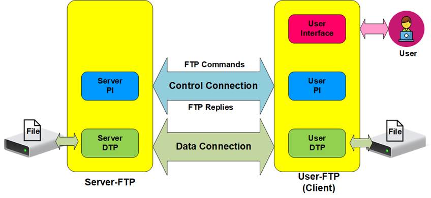
Figure 1 Model of FTP Use
In the model shown in Figure 1, two hosts with their own data storage participate in the FTP session: one host acts as the server, providing shared data over the network, and the other host functions as the client, allowing users to authenticate with credentials, typically a username and password. FTP requires two types of connections. The first is a control connection for transferring FTP commands and replies between the client and server, and the second is a data connection for the actual data transfer between two hosts.
The control connection is managed by the server-protocol interpreter (Server-PI) and the user-protocol interpreter (User-PI). The Server-PI listens on a dedicated port (commonly Port 21, as it is a well-known control port) until a connection is established. Once connected, the Server-PI waits for FTP commands from the User-PI, sends standard FTP replies in response, and manages the server data transfer process (Server-DTP) when command involves data transfer. On the client side, the User-PI forwards commands from the user interface to the Server-PI, wait for FTP replies, and manages the user data transfer process (User-DTP) as needed.
The data connection is managed by the server data transfer process (Server-DTP) and the user data transfer process (User-DTP) to facilitate data transmission. This connection can be initiated by either the Server-DTP (in active mode) or the User-DTP (in passive mode), with passive mode often preferred to address firewall restrictions on the FTP client. The data connection, used for transferring information or files, is terminated once the transfer is complete. Both the Server-DTP and User-DTP interact with their respective local file systems when reading or writing files.
The User Interface serves as an interface for individuals
requesting file transfer services through FTP software. Commands are issued by
the user, and responses are monitored.
1.1.1 FTP Connection Establishment and User Authentication
Once the user initiates a connection on the control port, the next step is user authentication, as the FTP server allow access only to authorized users. The connection establishment and login process details are as follows.
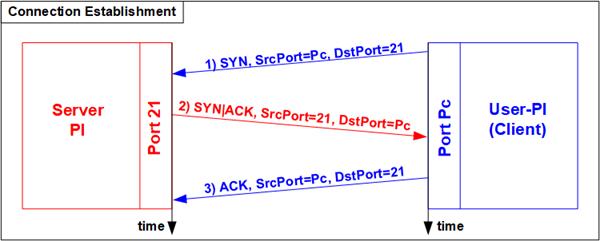
Figure 2 Connection Establishment on Control port
To establish a connection, FTP relies on the TCP 3-Way Handshake process, illustrated in Figure 2. The FTP client begins by sending a TCP packet with the SYN flag to the server on Port 21, requesting a new connection. Upon receiving this packet, the FTP server responds with a TCP packet containing both SYN and ACK flags, indicating acceptance of the connection request. Finally, the client sends an acknowledgement (ACK flag) to complete the handshake process after the control port is ready for communication between the server and client. This control port is then used to transfer FTP commands and replies.
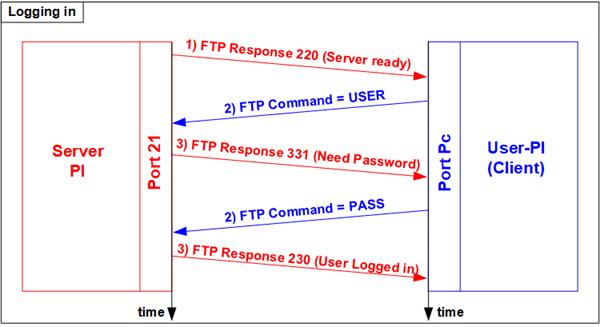
Figure 3 User Authentication
As shown in Figure 3, after the connection is established, authorized authenticate themselves by providing a valid username and password. For authentication, the client sends two FTP commands: the USER command with the username, followed by the PASS command with the password. Upon successful authentication, the server replies with FTP response 230, allowing the client to initiate a new session.
1.1.2 FTP Data Connection Management by Passive Mode
This reference design implements data connection establishment by the client (Passive mode), which is commonly used. Therefore, only the steps for Passive mode are described here.
Certain FTP commands, such as LIST (listing directories or files), STOR (storing files) and RETR (retrieving files), require a data connection to transfer information or files. Before data transfer in these commands, the client first sends the PASV command to specify parameters for the data connection, including the server’s IP address and port number for the Server-DTP.
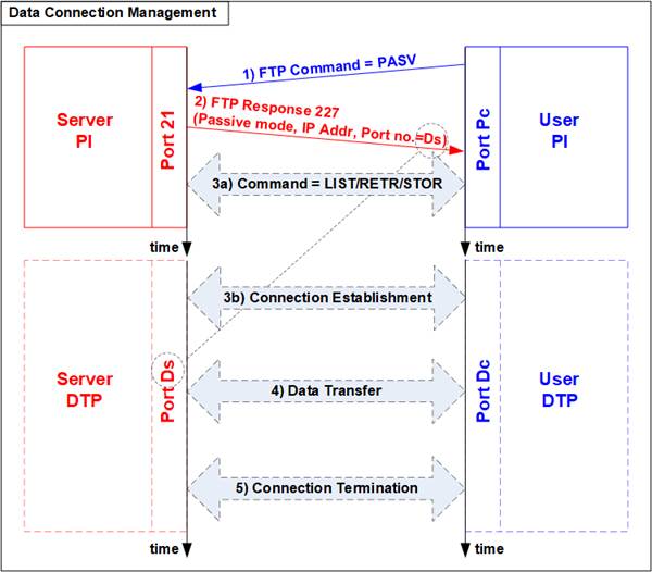
Figure 4 Data Connection Management in Passive Mode
Upon receiving the PASV command, the server responds with FTP response 227, providing the IP address and port number for the Server-DTP. Assume the server’s data port number is Ds. The Server-PI then instructs the Server-DTP to listen on Port Ds, awaiting the establishment of a data connection. Next, the User-PI sends an FTP command requiring data transfer to the Server-PI. Simultaneously, the User-DTP establishes the data connection to transfer data with the Server-DTP. The sequence of step 3a (sending the FTP command) and step 3b (establishing the data connection) may vary depending on the FTP client’s behavior. When the data transfer completes, the data connection is terminated by the data-sending side.
1.1.3 LIST Command
The LIST command is used to transfer information about files in a specified directory on the server through an established data connection. First, the User-PI (client) sends the PASV command to initialize the data connection. Then, the User-PI issues the LIST command to the Server-PI while the User-DTP simultaneously establishes the data connection. The order of step 2a (sending the LIST command) and step 2b (establishing the data connection) may vary depending on the client’s behavior.
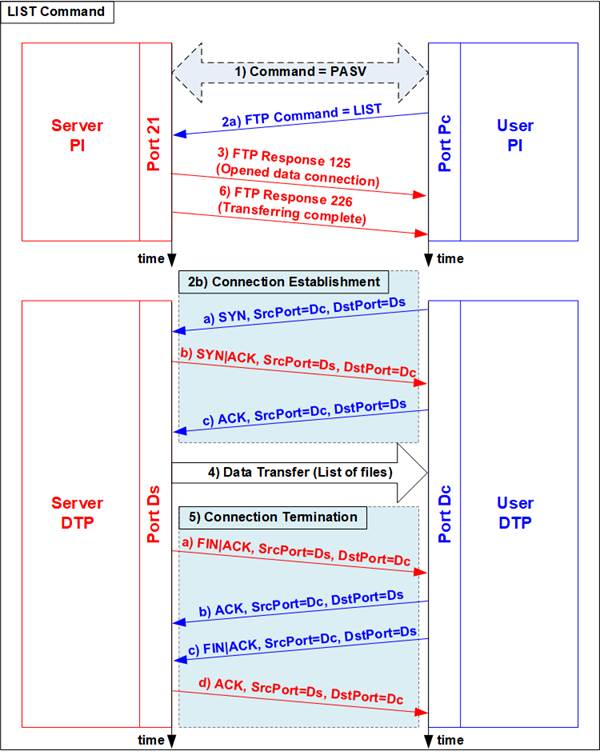
Figure 5 LIST Command Operation
For the server side, once the data connection is established, the Server-PI returns response 125 for the LIST command, and the Server-DTP transmits the file information or directory listing to the client. When data transfer is complete, the Server-DTP terminates the data connection, and the Server-PI sends response 226 to indicate the successful completion of the LIST command.
1.1.4 STOR Command
The STOR command is issued by client when the user wants to upload a file to the server’s storage. The client provides the file name for uploading with the STOR command. If a file with the same name already exists on the server, it will be replaced by the uploaded file; otherwise, a new file will be created. The server decodes the file name and prepares to store the incoming file. Data transmission then proceeds similarly to the LIST command but in the opposite direction, with data sent from the User-DTP (client) to the Server-DTP (server). Once all data has been transmitted, the User-DTP terminates the data connection.
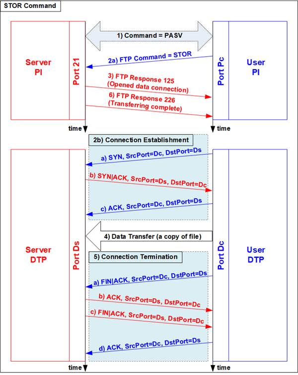
Figure 6 STOR Command Operation
1.1.5 RETR Command
The RETR command is sent by the client when the user requests to download a copy of a file from the server. The client includes the file name with the RETR command. On the server side, after decoding the file name, the server retrieves and transmits the data of the requested file. The sequence of data transfer steps is similar to the LIST command. Upon completion of the data transfer, the Server-DTP releases the data connection.

Figure 7 RETR Command Operation
1.2 FPGA-Based FTP Server for Two-User Access
Typically, an FPGA board directly connects to high-speed data sources, such as a radar system, to log data to storage at very high speeds. However, such systems lack real-time monitoring capabilities, requiring the system to be shut down to transfer the storage device from the FPGA system to a monitoring system located elsewhere.
In contrast, FPGAs are also widely used in High-Performance Computing (HPC) applications. In these applications, data processed by the FPGA is recorded to an SSD; however, a common challenge is managing continuous data input from the source. Without an additional interface, data for processing must be must be pre-loaded onto the FPGA, which can be inconvenient.
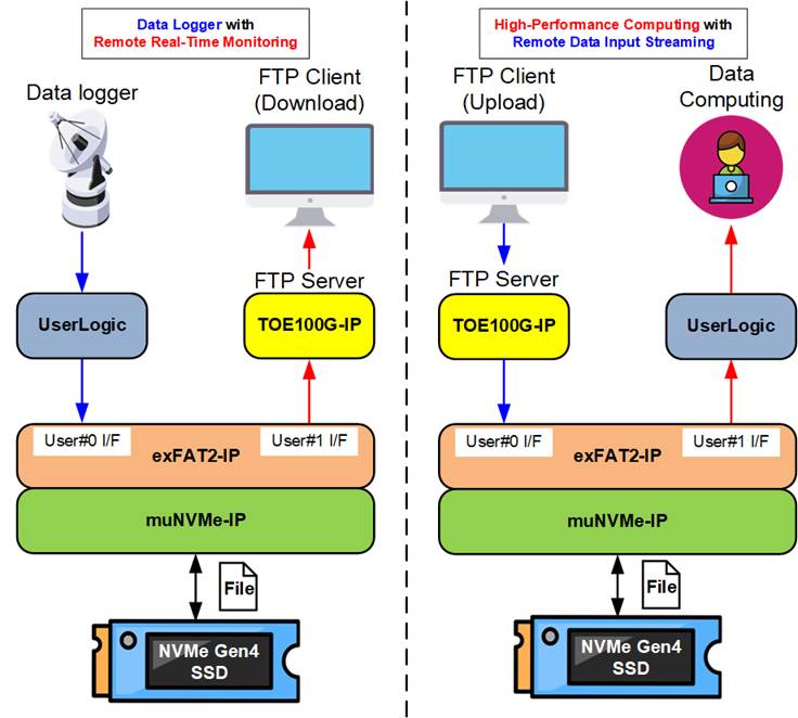
Figure 8 Hardware system for FTP Server by muNVMe-IP
To address these issues, this reference design implements an FPGA-based FTP server that enables simultaneous access to the SSD by two users. The first user is a remote PC that accesses the SSD via an FTP client, while the second user is local logic within the FPGA system. The two users can simultaneously access the SSD as long as they perform different data transfer operations – one use writes data, while the other reads data. Consequently, this system can serve as foundational solution for both high-speed data recording with real-time monitoring via FTP and high-performance computing with real-time data input streaming via FTP.
Further details of this FPGA-based reference design, including hardware and software components, are provided in the following sections. Section 2 details the hardware, while Section 3 describes the software running on the soft processor to manage the FTP server protocol.
2 Hardware
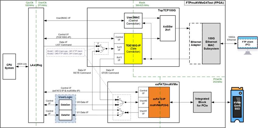
Figure 9 FTP Server by muNVMe-IP Reference Design
As mentioned in the introduction, the FTP server system uses two primary connections: a control connection for handling FTP commands and responses, and a data connection for transferring file information and file data during certain commands: LIST, STOR, and RETR.
The control connection is handled by the CPU system, where all control-related data is generated and monitored via the LAxi2Reg interface. FTP commands sent by the FTP client are first received by the User2MAC module, which forwards them from the 100G Ethernet MAC subsystem to the CPU for processing. Once the CPU processes these commands, it generates the FTP response, sending it back to the User2MAC module, which then forwards it to the FTP client via the 100G Ethernet MAC subsystem.
The data connection is managed by the TOE100G-IP and involves two main sources of data. The first is file information generated by the CPU system during the LIST command. The second is file data retrieved from the NVMe SSD using the exFAT2muNVMe module during the RETR command. For the STOR command, incoming data from the FTP client is directly transferred by the TOE100G-IP to the exFAT2muNVMe module for storage on the NVMe SSD.
The FTP server design enables simultaneous write and read operations using the exFAT2muNVMe module, which provides two user interfaces: User#0 for writing and User#1 for reading file data. During the RETR command, the FTP client retrieves file data via User#1 I/F while the DataGen submodule can update the SSD via User#0 I/F. Conversely, during the STOR command, the FTP client writes file data via User#0 I/F while the DataVer submodule can read file data via User#1 I/F.
Further details on each module inside the FTP server by muNVMe-IP system are described in subsequent sections.
2.1 100G Ethernet MAC Subsystem (100G BASE-SR)
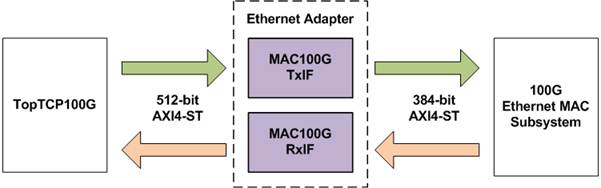
Figure 10 Adapter Logic of EMAC Interface for Versal Devices
This IP includes the MAC and PCS features but excludes the Transceiver module. A PMA module needs to be generated using the IP wizard in the tool for connecting to the 100G Ethernet MAC Subsystem. This user interface of Ethernet MAC (EMAC) can be configured to several modes, with this reference design using “Non-Segmented mode with independent clock” whose user interface is 384-bit. Since the user interface is incompatible with TOE100G-IP, two adapter logics, MAC100GTxIF and MAC100GRxIF, have been designed. The minimum clock frequency required for the 100G EMAC in this mode is 390.625 MHz. For more information, visit the AMD Xilinx website and check out the “PG314: Versal Devices Integrated 100G Multirate Ethernet MAC Subsystem Product Guide”.
https://www.xilinx.com/products/intellectual-property/mrmac.html
Note: The default reference design enables the RS-FEC feature on the 100G Ethernet (MAC) Subsystem. So, please ensure that the network equipment in the test environment supports RS-FEC feature. Contact us for the demo system that disables RS-FEC feature.
The adapter logics, MAC100GTxIF and MAC100GRxIF, are described in detail below.
2.1.1 MAC100GTxIF
This module serves as an AXI4-Stream converter, transitioning data from 512-bit to 384-bit format for data transfer from the TopTCP100G to the 100G Ethernet MAC Subsystem. In order to facilitate this transfer, a 384-bit register (rTempData) is used to store 128-bit user data for each cycle, which cannot be transmitted to the EMAC. The control signal, rTempCnt, indicates the quantity of unsent data in 128-bit units, stored in 384-bit internal register. Four distinct values are assigned to signify the data amount: 000b (No data), 001b (one 128-bit data), 011b (two 128-bit data), and 111b (three 128-bit data or full). The output data sent to EMAC is a mixed signal which combines user data (U2MACData) with the 384-bit rTempData, controlled by rTempCnt. Timing diagram to show more details of MAC100GTxIF is are shown in Figure 11.
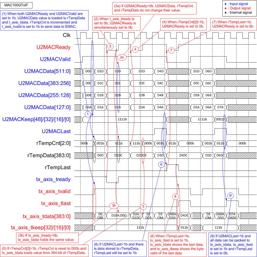
Figure 11 MAC100GTx Timing Diagram
1) Upon receiving the first data from the user (U2MACValid=1b and U2MACReady=1b while rTempCnt=000b), the module transfers 384-bit user data (U2MACData) to EMAC. ‘tx_axis_tvalid’ is asserted to 1b, and tx_axis_tdata loads the 384-bit data from U2MACData. If this data is not the last, the upper 128-bit unsent data is stored in the internal register (rTempData), and rTempCnt increments according to the sequence: 000b -> 001b -> 011b -> 111b. Additionally, tx_axis_tkeep is asserted to all ones to transfer the 384-bit data to EMAC.
2) When EMAC is not ready, tx_axis_tready is de-asserted to 0b. U2MACReady is also de-asserted to 0b, pausing the transmission of user data.
3) If tx_axis_tready and U2MACReady are de-asserted to 0b, the output signals to EMAC (tx_axis_tvalid, tx_axis_tlast, tx_axis_tdata, and tx_axis_tkeep) and the input signals from the user (U2MACValid, U2MACData, U2MACKeep, and U2MACLast) must retain the same values until the ready signals are re-asserted to 1b to accept the current data.
4) When the 384-bit register (rTempData) stores three 128-bit data, and rTempCnt equals 111b (indicating a full condition), U2MACReady is de-asserted to 0b to pause user data transmission. Subsequently, the 384-bit data from rTempData is flushed to EMAC.
5) ‘tx_axis_tdata’ loads 384-bit data from rTempData, and rTempCnt is reset to 000b, signifying no remaining unsent data stored in rTempData.
6) The last user data is transmitted by asserting U2MACLast to 1b. U2MACKeep is read to determine the number of valid bytes in the last data. Additionally, rTempCnt is read to check the amount of unsent data. In the provided example, one 128-bit data is stored in rTempCnt, and 512-bit user data is received, requiring the storage of two 128-bit data in rTempCnt. In such cases, rTempLast is asserted to 1b to store the unsent last data.
Note: Step 9) provides an example when the last user data is received, but all data can be transferred to EMAC without storing any data in rTempData.
7) rTempLast is asserted to 1b when the last user data is stored in rTempData. Simultaneously, U2MACReady is de-asserted to 0b, pausing user data transmission.
8) This step illustrates a scenario when two 128-bit data are stored in rTempData, and 128-bit last data is transmitted by user. Consequently, the total data, which comprises three 128-bit data, can be transferred to tx_axis_tdata by asserting tx_axis_tlast to 1b. In this case, no data is remained in rTempData, and rTempLast is not asserted to 1b.
2.1.2 MAC100GRxIF
This module functions as an AXI4-Stream converter, converting 384-bit data from the 100G Ethernet MAC Subsystem to a 512-bit format for transmission to the TopTCP100G. It includes a latch register to temporarily hold any unsent data not yest transmitted. The design uses three counters to handle data realignment. The first counter, wRx128bDataCnt, tracks the amount of data received from EMAC, ranging from 1 to 3 units of 128-bit data. The second counter, rLatDataCnt, shows the amount of unsent data held in the latch register, ranging from 0 to 3 units. The third counter, wRxTotalDataCnt, indicates the total count of received and unsent data, calculated as wRx128bDataCnt + rLatDataCnt, with a possible range of 1 to 6 units of 128-bit data.
When wRxTotalDataCnt is 4 or greater (5 or 6), a 512-bit data packet is assembled and transmitted to the TopTCP100G. However, the last transmitted data may be smaller than 512 bits, and this is controlled by the byte enable value (MAC2UKeep). The second counter (rLatDataCnt) is updated under various conditions.
1) Upon receiving the first data and there is no unsent data stored in rDataLat (rLatDataCnt=0), all bits of the first data are loaded into rDataLat. In this case, rLatDataCnt is set equal to the amount of data received from EMAC (wRx128bDataCnt), which is also equal to wRxTotalDataCnt when rLatDataCnt=0.
2) When the total data count (wRxTotalDataCnt) equals or exceeds 4, indicating that a 512-bit data is being transmitted to TopTCP100G, the unsent data count (rLatDataCnt) is reduced by 4 (wRxTotalDataCnt – 4).
3) Upon the transmission of the last data with no new packet received, the latch register becomes empty, and rLatDataCnt is reset to 0.
4) A special case arises when the last data is transmitted while the first data of a new packet is received. This scenario combines conditions 1) and 3), resulting in rLatDataCnt being set equal to the received data count of the new packet (wRx128bDataCnt).
The 384-bit latch register (rDataLat) utilizes rLatDataCnt to determine how much of the received data from EMAC must be retained in the next cycle.
1) If rLatDataCnt = 0, it stores three units of new 128-bit data (rx_axis_tdata[384:0]).
2) If rLatDataCnt = 3, one new 128-bit unit is packed with three previously stored 128-bit units (rDataLat[383:0]), and two units of new data (rx_axis_tdata[384:128]) are retained.
3) If rLatDataCnt = 2, two new 128-bit units are packed with two previously stored units (rDataLat[255:0]), and one new unit (rx_axis_tdata[384:256]) is retained.
4) If rLatDataCnt = 1, all new data is packed with one previously stored 128-bit unit (rDataLat[127:0]), and no data is retained in rDataLat.
To handle the transmission of the last data from EMAC to the TopTCP100G, two scenarios are considered.
1) If all the last data from EMAC can be packed with the contents of rDataLat (wRxTotalDataCnt ≤ 4), the last data is transmitted to the TopTCP100G in the next cycle.
2) If the total data count (wRxTotalDataCnt) for the last data exceeds 4, two cycles are required for complete transmission. A 512-bit data is sent during the first cycle, followed by any remaining data in the second cycle. The signal, rExLast, latches the last flag from EMAC for transmitting with the last data during the second cycle.
Timing diagram to show MAC100GRxIF operation is shown in Figure 12.
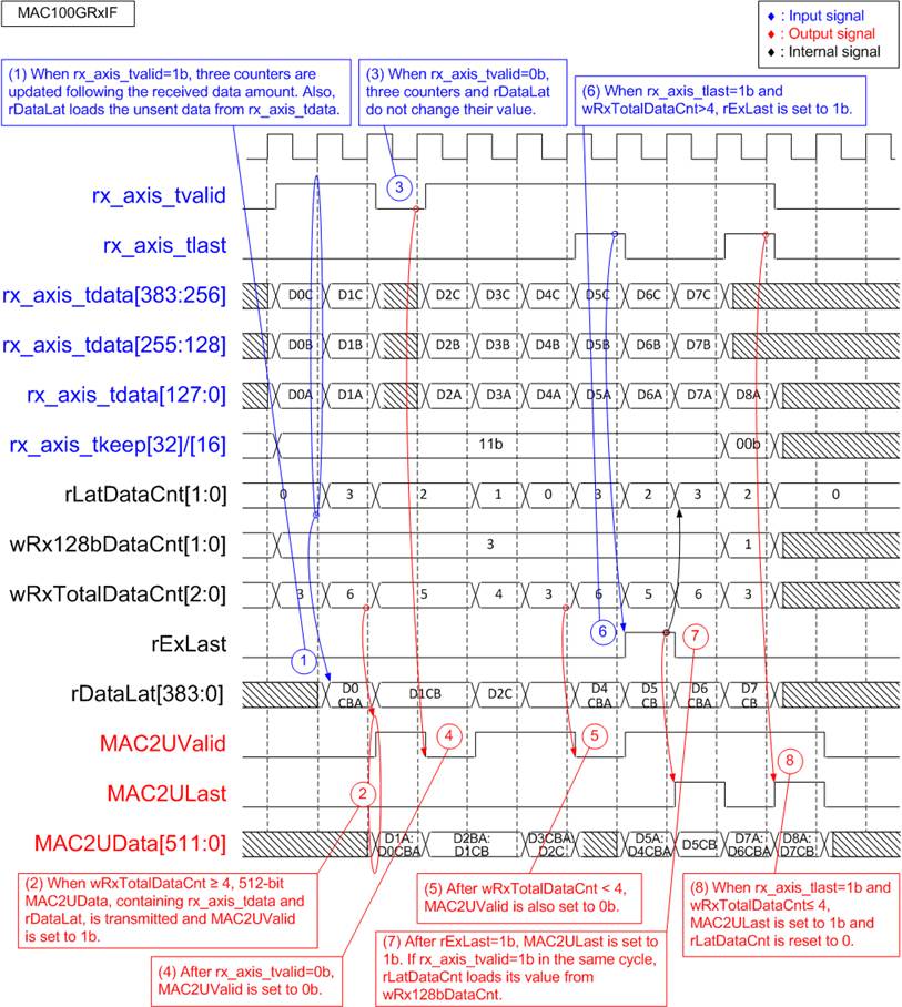
Figure 12 MAC100GRxIF Timing Diagram
1) Upon receiving new 384-bit data from EMAC, wRx128bDataCnt equals 3. If the previous clock cycle was Idle (rLatDataCnt=0), then wRxTotalDataCnt is equal to 3 (0+3). When rLatDataCnt is 0, the entire 384-bit data is loaded into rDataLat. Since wRxTotalDataCnt is less than 4, no data is transmitted to the MAC2U I/F.
2) When another 384-bit data arrives from EMAC with rLatDataCnt equal to 3 (indicating the amount of data stored in rDataLat from the previous clock cycle), wRxTotalDataCnt becomes 6 (3 + 3). This is sufficient to transmit data to MAC2U I/F. The signal, MAC2UValid, is asserted to 1b, facilitating the transmission of 512-bit M2UData. The M2UData consists of three 128-bit data (D0A, D0B, and D0C) from rDataLat and one 128-bit data (D1A) from rx_axis_tdata. The remaining two 128-bit data (D1B and D1C) are left unsent and stored in rDataLat, and rLatDataCnt is updated to 2.
3) If EMAC de-asserts rx_axis_tvalid to 0b, indicating it is not ready to transmit new data, the three counters (rLatDataCnt, wRx128bDataCnt, and wRxTotalDataCnt), along with rDataLat, maintain the same values, awaiting more data from EMAC.
4) When EMAC pauses data transmission by de-asserting rx_axis_tvalid to 0b, MAC2UValid is also de-asserted to 0b in the next clock cycle.
5) During the first cycle of every four cycles that receive 384-bit data from EMAC, if rLatDataCnt is equal to 0 and wRxTotalDataCnt is less than 4, MAC2UValid is de-asserted to 0b, pausing data transmission to the TopTCP100G.
6) When the last data is received from EMAC (rx_axis_tlast=1b and rx_axis_tvalid=1b) and wRxTotalDataCnt in that cycle is greater than 4 (5 or 6), the flag, rExLast, is asserted to 1b. Simultaneously, a 512-bit data is transmitted to the TopTCP100G, and any remaining data is sent in the subsequent cycle.
7) After rExLast is asserted to 1b, the signal, MAC2ULast, is also asserted to 1b to indicate the transmission of the remaining last data stored in rDataLat. If the first data of a new packet is immediately received from EMAC, it is loaded into rDataLat, and rLatDataCnt is updated with the count of 128-bit data units in the first cycle.
8) This case illustrates an example of sending the last data without asserting rExLast. When rx_axis_tlast is asserted to 1b and wRxTotalDataCnt is less than or equal to 4, the last data can be packed and sent to the TopTCP100G in the next cycle. Therefore, rExLast is not asserted to 1b, and rLatDataCnt is reset to 0.
2.2 TopTCP100G
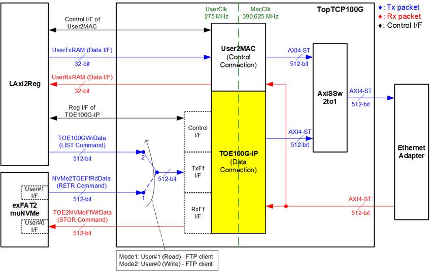
Figure 13 TopTCP100G Block Diagram
The TopTCP100G module manages all TCP packet transfers through the 100G Ethernet MAC subsystem, serving as the interface between the Ethernet hardware and the FTP server application. It utilizes two distinct TCP ports: one for the control connection, handling FTP commands and responses, and another for the data connection, which transfers file data or file information during the LIST, STOR, and RETR commands.
The control connection handles small FTP command packets via the User2MAC interface, which is controlled by the CPU. This interface is chosen due to the minimal traffic requirements of the control connection, allowing the CPU to efficiently decode commands and generate responses.
The data connection focuses on high-speed data transfers, particularly for large file operations requested by the FTP client during RETR or STOR commands. It utilizes the TOE100G-IP to achieve optimal performance, interfacing directly with high-speed NVMe SSD storage via the exFAT2muNVMe module. The data source for TOE10G-IP can switch between two options. First is the LAxi2Reg used by the CPU to generating file lists during the LIST command with low-speed access where each 512-bit data word is sent individually by the CPU. Second is the exFAT2muNVMe module, used during the RETR command to read file data from the SSD or during the STOR command to write file data to the SSD.
During the RETR command, the CPU calculates the total file size on the SSD and configures the transmit size for TOE100G-IP accordingly. For the STOR command, TOE100G-IP receives incoming data and transfers it to the exFAT2muNVMe module for storage on the NVMe SSD, continuing this process as long as there is space in the exFAT2muNVMe buffer and data available in the TOE100G-IP receive buffer.
The distinct port numbers assigned to the control and data connections allow the User2MAC and TOE100G-IP modules to filter and process only the packets intended for their respective ports, preventing any overlap in packet handling. Since Ethernet packets may be sent from either User2MAC or TOE100G-IP, the AxiSSw2to1 module is used to select the appropriate transmission source, dynamically updating the selection after each packet transmission to ensure efficient use of the Ethernet MAC subsystem.
2.2.1 User2MAC
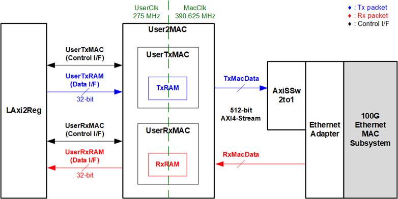
Figure 14 User2MAC Block Diagram
The User2MAC block is responsible for managing the FTP control connection by facilitating communication between the CPU and the Ethernet interface. The CPU communicates via the LAxi2Reg interface, a low-speed, 32-bit data bus, while the Ethernet interface operates on a high-speed, 512-bit AXI4 Stream interface. To bridge this difference, User2MAC incorporates buffers to handle both the mismatch in data width and the asynchronous clock domains.
The User2MAC block supports bidirectional data transfers, enabling simultaneous packet transmission and reception. It is composed of two key components: Transmission path and Reception path.
For transmission path, the CPU prepares and stores outgoing Ethernet packets in TxRAM, managed by transmission logic. Packets are then sent to the Ethernet interface for delivery.
For reception path, incoming Ethernet packets from the EMAC are stored in RxRAM. Before storage, a filtering mechanism checks the Ethernet headers, ensuing only valid packets are retained. Invalid packets are discarded. The CPU then retrieves the stored packets from RxRAM for decoding and processing.
Further details about UserTxMAC and UserRxMAC are provided below.
UserTxMAC
The UserTxMAC module is responsible for transmitting Ethernet packets from the CPU to the Ethernet interface. It utilizes a TxRAM, a 64 x 512-bit asynchronous dual-port RAM, to store packets prepared by the CPU via the UserTxRam Write I/F. The maximum packet size is 4096 bytes, corresponding to the size of TxRAM. The CPU defines the packet size using the UserTxMacLen register.
Once the packet is completely written into TxRAM, the CPU asserts UserTxMacReq to initiate transmission. Data is transferred from TxRAM to the Ethernet interface via the 512-bit AXI4 Stream interface. The transmission process pauses if the Ethernet interface de-asserts TxReady. The CPU monitors the operation’s status through the UserTxMacBusy signal, which changes from 1b to 0b upon completion. Figure 15 provides further details on the internal of UserTxMAC.
Note: UserTxMacLen is specified in byte units. TxRAM includes byte-enable functionality, allowing the CPU to write only some bytes of data. A decoder is also implemented to configure the TxKeep signal for the last packet data, ensuring alignment with the defined packet size.
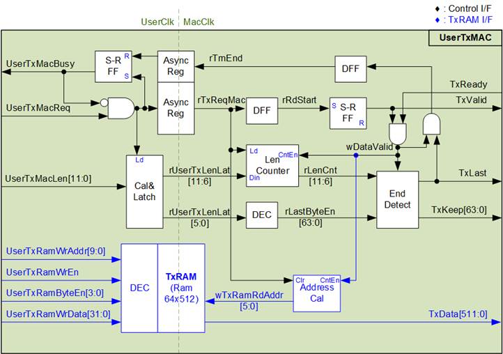
Figure 15 UserTxMAC Logic Diagram
The steps to transmit a packet from UserTxMAC are described as follows.
1) The CPU checks that UserTxMacBusy is 0b to confirm that UserTxMAC is in an Idle state.
2) The CPU prepares the packet to be transmitted and writes it to TxRAM, starting at address 0 (UserTxRamWrAddr equals 0). The maximum packet size is 4 KB, which is the total size of TxRAM.
3) The CPU sets UserTxMacLen to specify the packet size in bytes and asserts UserTxMacReq to 1b, initiating data transmission.
4) The request signal is transferred to the MacClk domain through the AsyncReg module. Simultaneously, UserTxMacBusy is asserted to 1b to indicate that transmission is in progress. The total transfer size (UserTxMacLen) is loaded into internal logic and split into two parts:
· The count of 512-bit data words, derived from UserTxMacLen[11:6], rounded up if the size is not a multiple of 512 bits.
· The remaining bits ([5:0]) are used to configure the byte enable signals for the final packet data (rLastByteEn and TxKeep) via a decoder.
5) When the start flag in the MacClk domain is asserted, the first packet data is read from TxRAM, and TxValid is asserted to 1b. The read address (wTxRamRdAddr) increments to fetch subsequent data after each transfer (TxValid=1b and TxReady=1b). The Length counter (rLenCnt) decrements with each data transfer to track the remaining data.
6) When rLenCnt=1 or the next data word is the last in the packet, the TxLast signal is asserted to 1b. The byte enable signal (TxKeep) is set using the value from rLastByteEn. For non-final data words, TxKeep is set to all ones to enable a full 512-bit transfer. After the last word is sent, the End flag (rTrnEnd) is asserted to de-assert UserTxMacBusy. The End flag is passed through the AsyncReg module to transfer it from the MacClk domain to the Clk domain
UserRxMAC
The UserRxMAC validates received Ethernet packets and stores valid packets into RxRAM, a 64 x 512-bit asynchronous dual-port RAM. The internal logic is designed to handle three key operations. First, it verifies the first 38 bytes of each received packet (byte#0 – byte#37) by comparing them with user-defined expected values and mask bits. Only packets with matching headers are accepted. Second, it checks the user-provided enable flag and ensures sufficient space is available in RxMacFf, a buffer that tracks the end address of RxRAM after storing a packet. If the module is disabled or if there is insufficient space in the buffer, the packet is rejected. The CPU determines the size of the received packet based on the end address stored in RxMacFf. Third, the module stores valid packets into RxRAM for further processing. Further details about the logic design of UserRxMAC are illustrated in Figure 16.
Note: The UserRxRam Read I/F for the CPU operates with a 32-bit data width, while RxRAM uses a 512-bit data width. A 16-to-1 multiplexer is included to allow the CPU access 32-bit data from the 512-bit memory.
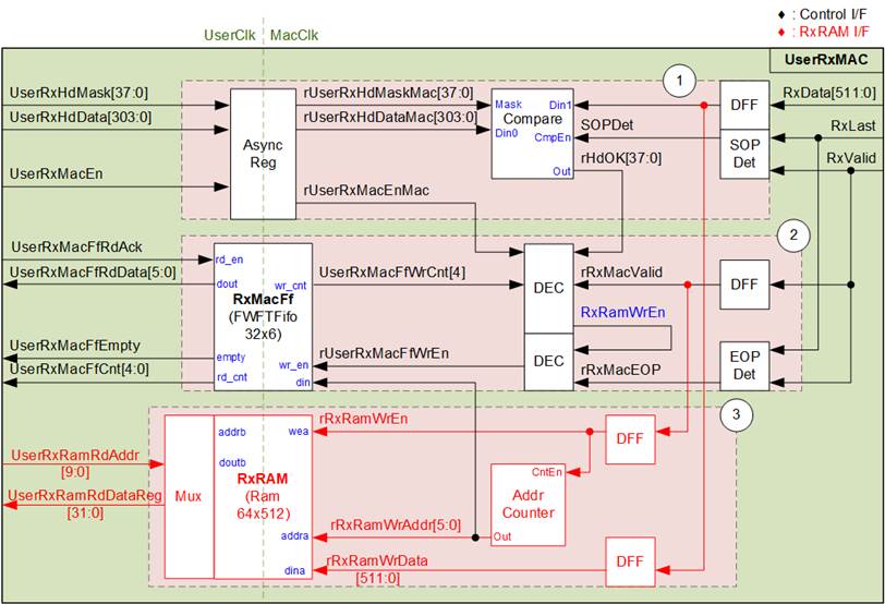
Figure 16 UserRxMAC Logic Diagram
As shown in Figure 16, the UserRxMAC module consists of three main components:
· Block (1): Verifies the 38-byte header of each packet.
· Block (2): Manges the storage of the end address in RxRAM.
· Block (3): Handles the storage of the received packet.
The operations of UserRxMAC when a packet is received are as follows.
1) The user configures two parameters: the 38-byte header data (UserRxHdData) and a 38-bit data mask (UserRxHdMask) for header verification. These parameters must remain stable when the user enables the module by asserting UserRxMacEn to 1b. The parameters are transferred through an AsyncReg for clock domain crossing. When the first data of a new packet is received, SOPDet signals the Compare module to begin header verification. The 38-byte header data is compared against byte#0 to byte#37 of received data, controlled by the data mask bits. A 0b value in a mask bit bypasses the corresponding data byte, efficiently disabling header verification if UserRxHdMask is all zeros. When the header is validated, rHdOK is asserted to 1b. A packet can be stored in RxRAM only if all 38 bits of rHdOK are all ones.
2) The module additionally checks the user enable flag (UserRxMacEn) and the RxMacFf data counter (UserRxMacFfWrCnt) to confirm readiness for packet processing. The user must assert UserRxMacEn to 1b and ensure sufficient space in RxMacFf by verifying that bit4 of UserRxMacFfWrCnt is 0. If these conditions are met and the header is valid, the RxRAM write enable signal (RxRamWrEn) is asserted, allowing the packet dat a to be stored in RxRAM. Upon reeiving the end of the packet (EOPDet), a pulse is generated to write the end address of RxRAM to RxMaFf. The rUserRxMacFfWrEn is asserted to 1b to perform this operation.
3) Valid packets are stored in RxRAM as the data is received (RxValid=1b) by asserting the rRxRamWrEn signal. The write address counter increments with each 512-bit data segment written to RxRAM. After the end-of-packet is received, the final address is stored in RxMacFf.
Note: Bit4 of UserRxMacFfWrCnt is used to check available FIFO space, allowing up to 16 addresses to be stored in RxMacFf. This corresponds to a maximum of 16 packets being stored in RxRAM. With the default RxRAM size of 4 KB, each packet should not exceed 256 bytes. However, the user can adjust the RAM and FIFO sizes to match the system requirements.
The CPU processes received packets stored in UserRxMAC as follows.
1) The CPU waits until the FIFO is not empty (UserRxMacFfEmpty=0b).
2) The CPU reads the last address from UserRxMacFfRdData, which is valid because RxMacFf is First Word Fall Through (FWFT) FIFO.
3) The CPU asserts UserRxMacFfRdAck to 1b to remove the read data from RxMacFf.
4) The CPU reads and decodes the packet from RxRAM, starting from the latest read position to the address read from RxMacFf. After processing the packet, the CPU returns to step 1 to handle the next packet.
Note: UserRxRamRdAddr is the address for 32-bit data, while rRxRamWrAddr represents the address for 512-bit data. The CPU firmware must convert the 512-bit address from RxMacFf to a 32-bit address before reading data from RxRAM.
The 38-byte header of the received packet for the FTP application’s control connection is illustrated in Figure 17.
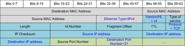
Figure 17 TCP/IP Packet Header for FTP Application
The packet filtering module, controlled by the CPU firmware, validates the 38-byte header against parameters configured by the CPU. In the demo, the CPU firmware enables filtering by setting the appropriate flags and defining the expected values for six fields in the header (highlighted in blue in Figure 17). These files are:
1) Ethernet Type (2 bytes) = 0800h (IPv4)
2) IP version (1 byte) = 45h (Version 4)
3) Protocol (1 byte) = 06h (TCP Protocol)
4) Source IP Address (4 bytes) = IP address of the FTP client
5) Destination IP address (4 bytes) = local IP address of the FPGA
6) Destination Port Number (2 bytes) = 0015h (Port 21)
Only packets with headers matching these parameters are stored in RxRAM for CPU processing. Packets that do not meet the criteria are ignored.
2.2.2 TOE100G-IP
The TOE100G-IP implements a fully offloaded TCP/IP stack, eliminating the need for CPU intervention and external memory. It provides two groups of user interfaces: control signals and data signals. The control signals use a Register interface for configuring parameters and monitoring status signals, while the data signals are accessed through a FIFO interface. Detailed information can be found in the datasheet.
https://dgway.com/products/IP/TOE100G-IP/dg_toe100gip_data_sheet_xilinx/
2.2.3 AxiSSw2to1
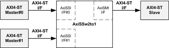
Figure 18 AxiSSw2to1 Interface
The AxiSSw2to1 module is a 2-to-1 switch for the AXI4-Stream (AXI4-ST) interface, enabling the transmission of data from User2MAC or TOE100G-IP to the Ethernet MAC subsystem. This module supports configurable parameters, allowing customization of data and user signal widths. In this design, the data width for User2MAC and TOE100G-IP is set to 512 bits, and the user signal width is set to 1 bit.
Conceptually, AxiSSw2to1 operates by transferring data from two Masters (Ch#0 and Ch#1) to a single Slave. When both channels request data transfer simultaneously, a priority mechanism selects the higher priority to completes its data transfer first. Once the packet transmission of the active channel finishes, the priority switches to the other channel for its data stream transfer.
The control signal ‘rChSel’ manages the channel selection logic within AxiSSw2to1. During an idle condition, if both channels request data transfer, ‘rChSel’ changes to the new channel after the current channel’s data transfer is completed.
Further details of the AxiSSw2to1 operation are illustrated in Figure 19.
1) When both channels simultaneously initiate packet transmission by asserting AxiSSlValid to 1b and the module is in an Idle state, the value of rChSel (indicating the active channel) remains unchanged. This ensures data continues to be forwarded from the currently selected channel. In Figure 19, Ch#0 is selected, and AxiSSlReady is asserted to 1b for Ch#0, enabling it to transmit the first packet data.
2) The input signals from the active channel (Ch#0), including AxiSSlLast[0] (indicating the end-of-packet) and AxiSSlData[511:0] (512-bit data), are forwarded as output signals to the Slave via the Master I/F (AxiSMtLast and AxiSMtData, respectively). Simultaneously, AxiSMtValid is asserted to 1b, initiating the transmission of the packet to the Slave.
3) If the Slave is not ready to accept data, indicated by AxiSMtReady being de-asserted to 0b, all output signals on the Master I/F retain their current values. Additionally, AxiSSlReady for the active channel is de-asserted to 0b, preventing further data transmission from the channel until the Slave resumes readiness.
4) When the Slave reasserts AxiSMtReady to 1b, the output signals to the Slave update with the next data word from the internal latch register (rMtDataLat). This latch temporarily stores data from the active channel when AxiSSlReady is asserted to 1b, ensuring no data is lost during a pause in transmission.
5) After the final packet data from the active channel is accepted by the Slave, the module checks for another active channel. If AxiSSlValid for another channel is asserted, rChSel switches to select the new channel. In Figure 19, the next active channel becomes Ch#1 (rChSel=1b), enabling it to transmit its data to the Slave.
6) The input signals from the new active channel (Ch#1), including AxiSSlLast and AxiSSlData, are forwarded as output signals to the Slave (AxiSMtLast and AxiSMtData), continuing until the final packet data is transmitted.
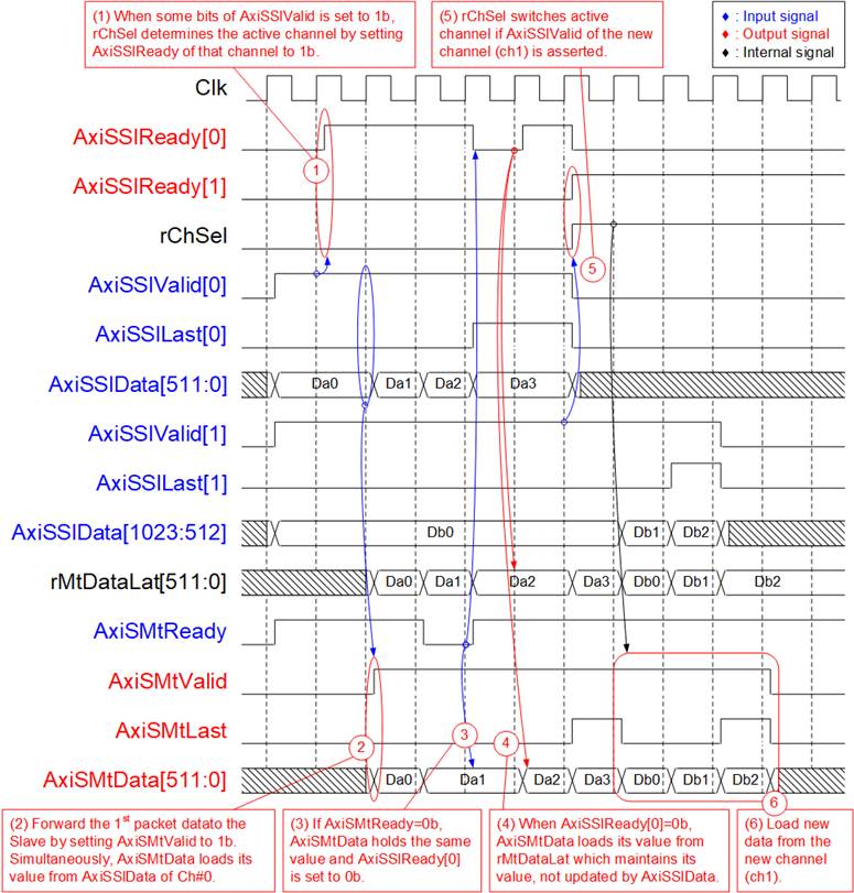
Figure 19AxiSSw2to1 Timing Diagram
2.3 exFAT2muNVMe
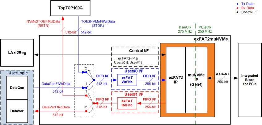
Figure 20 exFAT2muNVMe Block Diagram
The exFAT2muNVMe module manages data transfers to and from the NVMe SSD via the PCIe I/F. By combining exFAT2-IP with muNVMe-IP, the system supports simultaneous write and read operations from two users. The data interface uses a FIFO interface with two sources:
· TopTCP100G-IP: Transfers data with a remote target via the FTP client.
· UserLogic: Comprises the DataGen and DataVer modules.
A 2-to-1 multiplexer (MUX) facilitates the Write File operation, enabling data to be written from either DataGen module or TOE2NVMeFfWrData (STOR). For the Read File operation, data is transferred to DataVer or NVMe2TOEFfRdData (RETR).
To address the mismatch in data widths, an asymmetric FIFO is utilized. While TopTCP100G and UserLogic operate at a 512-bit width, exFAT2-IP functions at 256 bits. The exFATWrFifo and exFATRdFifo modules bridge this bit-width mismatch between the interfaces.
The control interface, responsible for setting file parameters and monitoring system status, is managed by the CPU via the LAxi2Reg module. Further details of the IP core involved are described below.
2.3.1 exFAT2-IP
The exFAT2-IP is an extension module of the muNVMe-IP designed by Design Gateway. It allows data storage and retrieval on the NVMe SSD using the exFAT file system while maintaining performance of a raw data format. Further information about the exFAT2-IP can be found in its datasheet:
https://dgway.com/products/IP/NVMe-IP/dg_exfat2ip_data_sheet_g4_amd/
2.3.2 muNVMe-IP Gen4
The muNVMe-IP implements the NVMe protocol on the host side, enabling direct access to the NVMe SSD without requiring a PCIe switch. It directly connects to the PCIe hard IP for seamless operation. For additional details, refere to its datasheet:
https://dgway.com/products/IP/NVMe-IP/dg_munvme_ip_data_sheet_g4_xilinx/
2.4 UserLogic
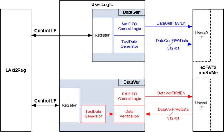
Figure 21 DataGen and DataVer Interface
The UserLogic module consists of two submodules: DataGen and DataVer, each operating independently. The CPU configures their parameters via the LAxi2Reg, including the file name, file size, number of files, enable flag, and test pattern. These parameters are stored in the internal Register File within both DataGen and DataVer.
DataGen is responsible for generating file data and transferring it to the exFAT2muNVMe module via a 512-bit data bus via a FIFO interface. It includes logic for data flow control, which pauses data transmission when the User#0 I/F is not ready, and for generating test patterns at the highest data rate supported by User#0 I/F.
DataVer receives and verifies file data from the exFAT2muNVMe module through a 512-bit data bus via a FIFO interface. Like DataGen, it incorporates data flow control logic to pause reception when no data is available for reading. It also includes logic to generate test patterns for verification and verify the received data through the User#1 I/F.
Further details about DataGen and DataVer are provided in the subsequent sections.
2.4.1 DataGen
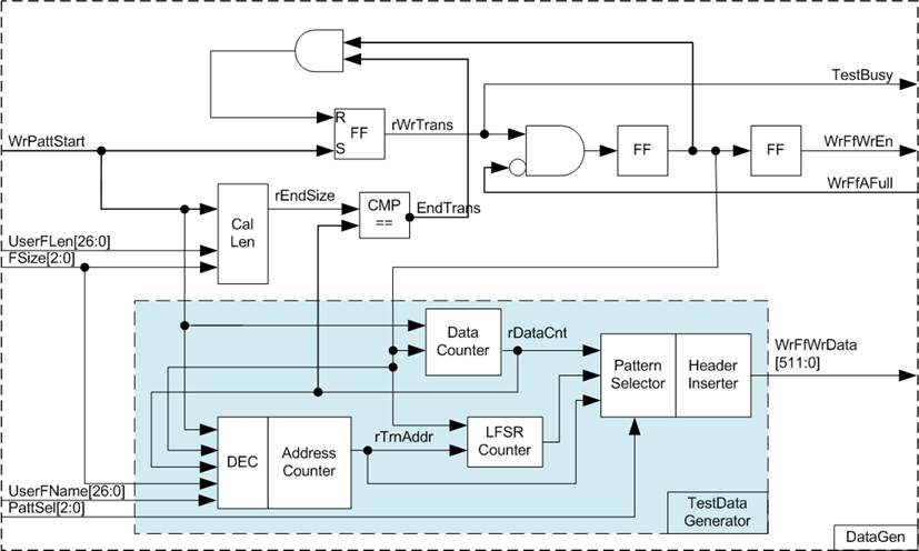
Figure 22 DataGen Block Diagram
The DataGen module allows the CPU to configure test parameters such as the number of files (UserFLen), file size (FSize), the first file name (UserFName), and test pattern selector (PattSel). The values of UserFLen and FSize are used to determine the end position (rEndSize) for the data transfer. Once the total data count (rDataCnt) reaches this value, EndTrans is asserted, marking the completion of the transfer and changing the busy status signal (TestBusy) from 1b to 0b.
The flow control mechanism relies on the WrFfAFull signal. When WrFfAFull is 0, it indicates that the User#0 I/F is ready to receive data. This leads to the assertion of WrFfWrEn to 1b, enabling data transmission to the User#0 I/F via the FIFO interface. The timing diagram illustrating this operation is shown in Figure 23.
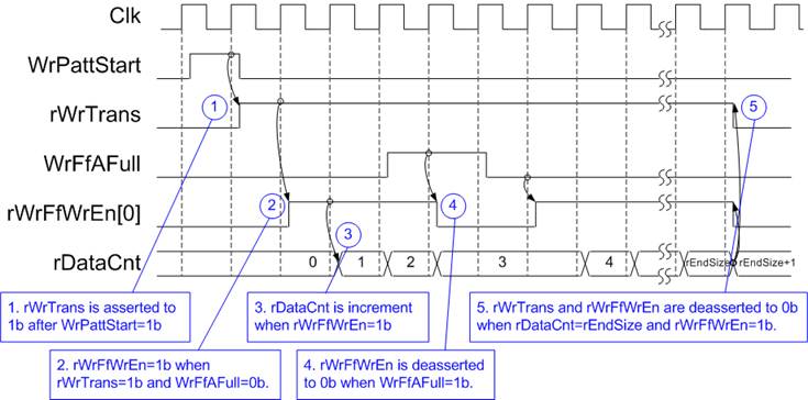
Figure 23 DataGen Timing
Diagram
1) The write operation begins when the WrPattStart signal is set to 1b for a single clock cycle. This triggers the assertion of rWrTrans, enabling data transmission to the FIFO.
2) The data is transmitted to the FIFO by asserting rWrFfWrEn to 1b when two conditions are met:
· The write operation is active, indicated by rWrTrans being 1b.
· The User#0 I/F is ready to receive data, indicated by WrFfAFull being 0b.
3) Also, rWrFfWrEn feeds back to the internal counter, allowing it to track the total count of transmitted data during the operation.
4) If the User#0 I/F becomes unavailable by asserting WrFfAFull to 1b, data transmission is paused by de-asserting rWrFfWrEn to 0b.
5) When the total data count (rDataCnt) reaches the user-defined end value (rEndSize), the transfer is completed. At this point, both rWrTrans and rWrFfWrEn are de-asserted to 0b, signaling the end of the operation.
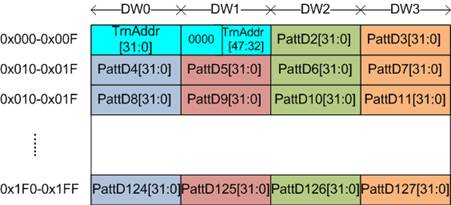
Figure 24 512-byte Data Segment for Increment/Decrement/LFSR Test Pattern
The TestData Generator is responsible for generating test data, whose pattern is defined by user via PattSel signal to be 32-bit incremental data, 32-bit decremental data, LFSR pattern, all zeros, or all ones. As shown in Figure 24, each 512-byte data segment generally includes a 64-bit header data and a test pattern, except two patterns: all zeros and all ones. Since all zeros and all ones are designed to show the best transfer performance in specific SSD, the all data in each 512-byte segment is filled by zero or one values without any header.
The 64-bit header, placed in Dword#0 and Dword#1, is generated using the address in 512-byte units (rTrnAddr), which is managed by the Address counter block. The initial value of the Address counter is computed based on the UserFName and FSize parameters and is incremented after each 512-byte data transfer.
The remaining data in Dword#2 to Dword#127 is the test pattern, which can be one of the following:
· 32-bit incremental data: Generated by the Data counter.
· 32-bit decremental data: Created by applying a NOT operation to the incremental data.
· LFSR pattern: Generated using the LFSR counter with the polynomial equation: x^31 + x^21 + x + 1.
For the LFSR pattern, the 512-bit data is divided into four 128-bit segments, each with a unique start value, as illustrated in Figure 25.
The look-ahead technique is employed to generate four 32-bit LFSR values (or one 128-bit data) per clock cycle. These values, represented in Figure 25 by matching colors, are derived from a combination of the 32-bit of LBAAddr and a NOT operation applied to specific bits of the LBAAddr (referred to as LBAAddrB). This ensures unique start values for each 128-bit data set.
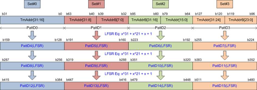
Figure 25 512-bit LFSR Pattern
2.4.2 DataVer
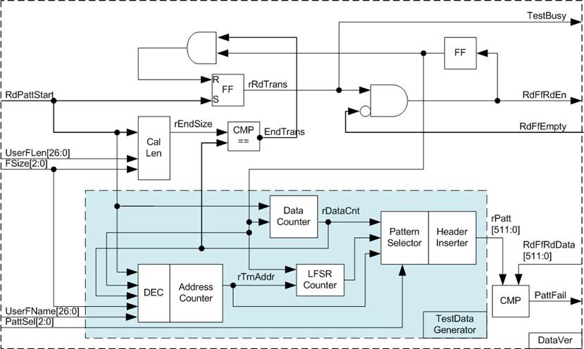
Figure 26 DataVer Block Diagram
Similar to DataGen, the DataVer module includes a Register file to store test parameters, including UserFLen, FSize, UserFNamee, and PattSel. A TestData Generator is also incorporated to generate the expected data for verifying the received data from the User#1 I/F. Once the total data count of the received data reaches the user-defined end position, the busy status (TestBusy) is updated from 1b to 0b, indicating the data transfer is completed.
The flow control mechanism relies on the RdFfEmpty signal. When RdFfEmpty is 0, it indicates that the User#1 I/F has data available for reading. This triggers the assertion of RdFfRdEn to 1, enabling data to be received via the FIFO interface. The received data is then compared with the expected data generated by the TestData Generator. If a mismatch occurs during this comparison, the failure flag is asserted to 1b, indicating an error.
2.5 CPU and Peripherals
In the reference design, the CPU system is extended with an additional peripheral to access the test logic. Therefore, the hardware logic must support the AXI4-Lite bus standard to allow for CPU-initiated write and read operations. The LAxi2Reg module facilitates this connection, as shown in Figure 27.
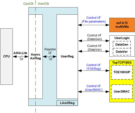
Figure 27 LAxi2Reg Block Diagram
UserReg contains the Register file for parameters and status signals associated with the test system, including the exFAT2muNVMe (exFAT2-IP and muNVMe-IP), UserLogic (DataGen and DataVer), and TopTCP100G (TOE100G-IP and User2MAC).
Further details on the operations of AsyncAxiReg and UserReg are provided in subsequent sections.
2.5.1 AsyncAxiReg
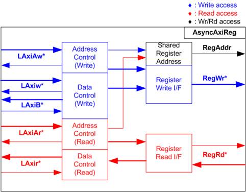
Figure 28 AsyncAxiReg Interface
The signals on AXI4-Lite bus interface are divided into five groups: LAxiAw* (Write address channel), LAxiw* (Write data channel), LAxiB* (Write response channel), LAxiAr* (Read address channel), and LAxir* (Read data channel). For more information on designing custom logic for the AXI4-Lite bus, refer to the following documentation.
In accordance with the AXI4-Lite standard, the write and read channels operate independently, with separate control and data interfaces for each channel. Therefore, the logic inside AsyncAxiReg that interfaces with the AXI4-Lite bus is divided into four functional groups: Write control logic, Write data logic, Read control logic, and Read data logic, as depicted on the left side of Figure 28. The Write control I/F and Write data I/F of the AXI4-Lite bus are latched and then transferred to the Write register interface via clock domain crossing registers. Similarly, the Read control I/F of the AXI4-Lite bus is latched and transferred to the Read register interface. The data returned from the Register Read I/F is transferred back to the AXI4-Lite bus by using clock domain crossing registers. In the Register interface, RegAddr is shared between write and read access, so the address is loaded from LAxiAw for write access or from LAxiAr for read access.
The simple register interface is designed to be compatible with a single-port RAM interface for write transaction. For read transaction, the Register interface is slightly modified from the RAM interface by adding RdReq and RdValid signals to control read latency. Since the address of the Register interface is shared for both write and read transactions, the user cannot perform simultaneous write and read operations. The timing diagram for the Register interface is shown in Figure 29.

Figure 29 Register Interface Timing Diagram
1) Timing diagram to write register is similar to that of a single-port RAM. The RegWrEn signal is set to 1b, along with a valid RegAddr (Register address in 32-bit units), RegWrData (write data for the register), and RegWrByteEn (write byte enable). The byte enable is four bits wide, where each bit indicates the validity of a specific byte within RegWrData. For example, if RegWrByteEn[0], [1], [2], and [3] are set to 1b, then RegWrData[7:0], [15:8], [23:16], and [31:24] are valid, respectively.
2) To read from a register, AsyncAxiReg sets the RegRdReq signal to 1b, along with a valid value for RegAddr. After the read request is processed, the 32-bit data is returned. The slave detects the RegRdReq being asserted to start the read transaction. During the read operation, the address value (RegAddr) remains unchanged until RegRdValid is set to 1b. Once valid, the address is used to select the returned data through multiple layers of multiplexers.
3) The slave returns the read data on RegRdData bus by setting the RegRdValid signal to 1b. After that, AsyncAxiReg forwards the read value to the LAxir* interface.
2.5.2 UserReg
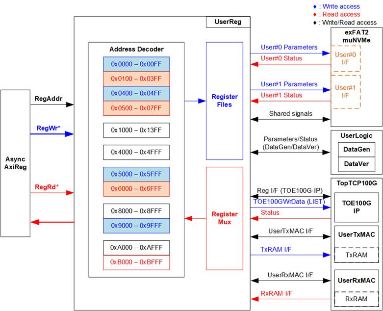
Figure 30 UserReg Interface
The UserReg module consists of an Address Decoder, Register Files, and Register Mux. The Address decoder interprets address requested by AsyncAxiReg to select the active register for write or read transactions. The address range in UserReg is divided into three groups, further subdivided into 10 areas, as illustrated in Figure 30.
exFAT2muNVMe and UserLogic
1) 0x0000 – 0x03FF: Mapped to User#0 of exFAT2muNVMe and UserLogic (DataGen).
2) 0x0400 – 0x07FF: Mapped to User#1 of exFAT2muNVNe and UserLogic (DataVer).
3) 0x1000 – 0x13FF: Mapped to other interfaces of exFAT2muNVMe, such as IP version information.
TopTCP100G
4) 0x4000 – 0x4FFF: Mapped to Reg I/F of TOE100G-IP for parameter configuration and monitoring.
5) 0x5000 – 0x5FFF: Mapped to transmitted data during the LIST command.
6) 0x6000 – 0x6FFF: Mapped to status signals of TopTCP100G.
User2MAC
7) 0x8000 – 0x8FFF: Control and status signals of UserTxMAC.
8) 0x9000 – 0x9FFF: Write interface of UserTxRAM within UserTxMAC.
9) 0xA000 – 0xAFFF: Control and status signals of UserRxMAC.
10) 0xB000 – 0xBFFF: Read interface of UserRxRAM within UserRxMAC.
For read transactions, a multi-level Register Mux selects the data to be returned return to the CPU based on the address. The lower bits of RegAddr are used to choose the active data within the submodule, while the upper bits select the active submodule. The total latency for returning read data is four clock cycles, during which RegRdValid is generated by propagating RegRdReq through three D Flip-flops. Further details of address mapping within the UserReg module are provided in Table 1.
Table 1 Register Map of FTP Server by muNVMe-IP
|
Address |
Register Name |
Description |
|
Rd/Wr |
(Label in ‘ftpmunvmeg4test.c’) |
|
|
0x0000 – 0x3FFF: Signal Interface of exFAT2muNVMe and UserLogic |
||
|
0x0000 – 0x00FF: Control signals of exFAT2-IP (User#0) and DataGen (Write access only) |
||
|
BA+0x0000 |
User#0 File Name Reg |
[26:0]: Input to U0FName of exFAT2-IP, the first file name to execute write file command. |
|
(U0FNAME_INTREG) |
||
|
BA+0x0004 |
User#0 File Length Reg |
[26:0]: Input to U0Flen of exFAT2-IP, the total number of files requested in write command. |
|
(U0FLEN_INTREG) |
||
|
BA+0x0008 |
User#0 Command Reg |
[2:0]: Input to U0Cmd of exFAT2-IP, commands. 000b: Format, 001b: Shutdown, 010b: Write file, 011b: Read file, 100b: Secure Format, 101b: Read file info [8]: Input to U0Req of exFAT2-IP, command request. |
|
(U0CMD_INTREG) |
||
|
BA+0x000C |
DataGen Test Pattern Reg |
[2:0]: Select test data pattern of DataGen. 000b-Increment, 001b-Decrement, 010b-All 0, 011b-All 1,100b-LFSR |
|
(DATAGENPATTSEL_INTREG) |
||
|
BA+0x0018 |
DataGen Enable Reg |
[0]: Enable flag for DataGen. |
|
(DATAGENEN_INTREG) |
||
|
BA+0x0020 |
User#0 File Size Reg |
[3:0]: Input to U0FSize of exFAT2-IP, configured file size. |
|
(U0FSIZE_INTREG) |
||
|
BA+0x0024 |
User#0 Created Date and Time Reg |
[4:0]: Input to U0FTimeS of exFAT2-IP, second multiplied by 2. [10:5]: Input to U0FTimeM of exFAT2-IP, minute. [15:11]: Input to U0FTimeH of exFAT2-IP, hour. [20:16]: Input to U0FDateD of exFAT2-IP, date. [24:21]: Input to U0FDateM of exFAT2-IP, month. [31:25]: Input to U0FDateY of exFAT2-IP, year. |
|
(U0DATETIME_INTREG) |
||
|
0x0100 – 0x03FF: Status signals of exFAT2-IP (User#0) and DataGen (Read access only) |
||
|
BA+0x0100 |
User#0 Status Reg |
[0]: Mapped to U0Busy of exFAT2-IP, busy status. [1]: Mapped to U0Error of exFAT2-IP, error flag. [2]: Mapped to DataGenBusy of DataGen |
|
(U0STS_INTREG) |
||
|
BA+0x0104 |
User#0 Error Type Reg |
[7:0]: Mapped to U0ErrorType[7:0] of exFAT2-IP, indicating error status of exFAT2-IP. |
|
(U0ERRTYPE_INTREG) |
||
|
BA+0x0108 |
User#0 NVMe Error Type Reg |
[31:0]: Mapped to U0NVMeErrorType[31:0] of exFAT2-IP, indicating error status of muNVMe-IP. |
|
(U0NVMERRTYPE_INTREG) |
||
|
BA+0x0120 |
User#0 Test Pin (Low) Reg |
[31:0]: Mapped to U0TestPin[31:0] of exFAT2-IP, reserved for internal use. |
|
(U0TESTPINL_INTREG) |
||
|
BA+0x0124 |
User#0 Test Pin (High) Reg |
[63:32]: Mapped to U0TestPin[63:0] of exFAT2-IP, reserved for internal use. |
|
(U0TESTPINH_INTREG) |
||
|
BA+0x0128 |
User#0 NVMe Test pin (Low) Reg |
[31:0]: Mapped to U0TestPin[31:0] of muNVMe-IP, reserved for internal use. |
|
(U0NVMTESTPINL_INTREG) |
||
|
BA+0x012C |
NVMe User#0 Test pin (High) Reg |
[47:32]: Mapped to U0TestPin[47:32] of muNVMe-IP, reserved for internal use. |
|
(NVMU0TESTPINH_INTREG) |
||
|
BA+0x0140 |
Total File Capacity Reg |
[26:0]: Mapped to TotalFCap[26:0] of exFAT2-IP, maximum number of files for this SSD. |
|
(TOTALFCAP_INTREG) |
||
|
BA+0x0144 |
Directory Capacity Reg |
[19:0]: Mapped to DirCap[19:0] of exFAT2-IP, maximum number of files for each directory. |
|
(DIRCAP_INTREG) |
||
|
BA+0x0148 |
Disk File Size Reg |
[3:0]: Mapped to DiskFsize of exFAT2-IP, file size currently used in this SSD. |
|
(DFSIZE_INTREG) |
||
|
Address |
Register Name |
Description |
|
Rd/Wr |
(Label in ‘ftpmunvmeg4test.c’) |
|
|
0x0100 – 0x03FF: Status signals of exFAT2-IP (User#0) and DataGen (Read access only) |
||
|
BA+0x014C |
Total Count of Files in the Disk Reg |
[26:0]: Mapped to DiskFnum of exFAT2-IP, total count of files in the SSD. |
|
(DFNUM_INTREG) |
||
|
BA+0x0150 |
Current Total Count of Files in the Disk Reg |
[26:0]: Mapped to DiskFnumCur of exFAT2-IP, current total count of files in the SSD.
|
|
(DFNUMCUR_INTREG) |
||
|
BA+0x0160 |
NVMe LBA Size (Low) Reg |
[31:0]: Mapped to LBASize[31:0] of muNVMe-IP, total capacity of SSD in 512-byte unit. |
|
(NVMLBASIZEL_INTREG) |
||
|
BA+0x0164 |
NVMe LBA Size (High) Reg |
[15:0]: Mapped to LBASize[47:32] of muNVMe-IP, total capacity of SSD in 512-byte unit. [30]: Mapped to SuppSecureFmt of exFAT2-IP, Secure Format supported flag. [31]: Mapped to LBAMode of muNVMe-IP, indicating SSD LBA unit size. |
|
(NVMLBASIZEH_INTREG) |
||
|
BA+0x0168 |
User#0 NVMe Completion Status Reg |
Completion Status from muNVMe-IP [15:0]: Mapped to U0AdmCompStatus[15:0]. [31:16]: Mapped to U0IOCompStatus[15:0]. |
|
(NVMCOMPSTS_INTREG) |
||
|
BA+0x016C |
NVMe CAP Reg |
[31:0]: Mapped to NVMeCAPReg[31:0] of muNVMe-IP, capabilities of NVMe. |
|
(NVMCAP_INTREG) |
||
|
BA+0x0200 |
User#0 Current Test Data in Bytes (Low) Reg |
[31:0]: Bits[31:0] of the current data transfer size in bytes when operating Write file command. |
|
(U0CURTESTSIZEL_INTREG) |
||
|
BA+0x0204 |
User#0 Current Test Data in Bytes (High) Reg |
[24:0]: Bits[56:32] of the current data transfer size in bytes when operating Write file command. |
|
(U0CURTESTSIZEH_INTREG) |
||
|
0x0400 – 0x04FF: Control signals of exFAT2-IP (User#1) and DataVer (Write access only) Note: The base address of User#1 register sets is determined by the offset value from User#0 register sets. The specific offset value is assigned using the parameter name ‘USEROFFSET_INT’. |
||
|
BA+0x0400– BA+0x040B |
User#1 File Name Reg – User#1 Command Reg |
Match the registers of User#0 at 0x0000 – 0x000B. However, the User#1 Command Reg supports only Read file and Read file info operations. |
|
BA+0x040C |
DataVer Test Pattern Reg |
[2:0]: Select test data pattern of DataVer. 000b-Increment, 001b-Decrement, 010b-All 0, 011b-All 1,100b-LFSR |
|
(DATAVERPATTSEL_INTREG) |
||
|
BA+0x0418 |
DataVer Enable Reg |
[0]: Enable flag for DataVer. |
|
(DATAVEREN_INTREG) |
||
|
0x0500 – 0x07FF: Control signals of exFAT2-IP (User#1) and DataVer (Read access only) |
||
|
BA+0x0500 |
User#1 Status Reg |
[0]: Mapped to U1Busy of exFAT2-IP, busy status. [1]: Mapped to U1Error of exFAT2-IP, error flag. [2]: Mapped to DataVerBusy of DataVer [3]: Data verification fail of DataVer (0b: Normal, 1b: Error). |
|
(U1STS_INTREG) |
||
|
BA+0x0504 |
User#1 Error Type Reg |
[7:0]: Mapped to U1ErrorType[7:0] of exFAT2-IP, indicating error status of exFAT2-IP. |
|
(U1ERRTYPE_INTREG) |
||
|
BA+0x0508 |
User#1 NVMe Error Type Reg |
[31:0]: Mapped to U1NVMeErrorType[31:0] of exFAT2-IP, indicating error status of muNVMe-IP. |
|
(U1NVMERRTYPE_INTREG) |
||
|
BA+0x0510 |
User#1 File Info Reg |
[31:0]: Mapped to U1FInfo of exFAT2-IP, modified date and time of file. |
|
(U1FINFO_INTREG) |
||
|
BA+0x0520– BA+0x052F |
User#1 Test Pin Reg – User#1 NVMe Test Pin Reg |
Match the registers of User#0 at 0x0120 – 0x012F. However, the User#1 Test Pin Reg and User#1 NVMe Test Pin Reg can be mapped using a single register. The High Reg is not required. |
|
BA+0x0568 |
User#1 NVMe Completion Status Reg |
Match the registers of User#0 at 0x0168. However, the User#1 Completion status indicate on IOCompStatus register. The AdmCompStatus is not required. |
|
Address |
Register Name |
Description |
|
Rd/Wr |
(Label in ‘ftpmunvmeg4test.c’) |
|
|
0x0000 – 0x3FFF: Signal Interface of exFAT2-IP and DataGen and DataVer |
||
|
0x0500 – 0x07FF: Control signals of exFAT2-IP (User#1) and DataVer (Read access only) |
||
|
BA+0x0600– BA+0x0607 |
User#1 Current Test Data in Bytes (Low) Reg – User#1 Current Test Data in Bytes (High) Reg |
Match the registers of User#0 at 0x0200 – 0x0207. However, the User#1 Current Test Data in Bytes Reg indicates data transfer size when operating Read file command |
|
BA+0x0610 |
DataVer Failure Byte Address (Low) Reg |
[31:0]: Bits[31:0] of the byte address in the file at the 1st failure data in DataVer when operating Read file command. |
|
(U1FAILADDRL_INTREG) |
||
|
BA+0x0614 |
DataVer Failure Byte Address (High) Reg |
[6:0]: Bits[38:32] of the byte address in the file at the 1st failure data in DataVer when operating Read file command. |
|
(U1FAILADDRH_INTREG) |
||
|
BA+0x0618 |
DataVer Failure File Name Reg |
[26:0]: Filename of the 1st failure data in DataVer when operating Read file command. |
|
(U1FAILFNAME_INTREG) |
||
|
BA+0x0680– BA+0x06BF |
DataVer Expected value Word0-15 Reg |
512-bit of the expected data at the 1st failure data in DataVer when operating Read file command 0x0280: Bits[31:0], 0x0284: Bits[63:32], …, 0x02BC: Bits[511:480] |
|
(U1EXPPATW0-15_INTREG) |
||
|
BA+0x06C0– BA+0x06FF |
DataVer Read value Word0-15 Reg |
512-bit of the read data at the 1st failure data in DataVer when operating Read file command 0x02C0: Bits[31:0], 0x02C4: Bits[63:32], …, 0x02FC: Bits[511:480] |
|
(U1RDPATW0-15_INTREG) |
||
|
0x1000 – 0x13FF: Other interfaces of exFAT2-IP and muNVMe-IP |
||
|
BA+0x1000 Wr |
Timeout Reg |
[31:0]: Mapped to TimeOutSet[31:0] of exFAT2-IP, timeout value for waiting for a response from SSD. |
|
(TIMEOUT_INTREG) |
||
|
BA+0x1200 Rd |
exFAT2-IP Version Reg |
[31:0]: Mapped to IPVersion[31:0] of exFAT2-IP, indicating the version of exFAT2-IP. |
|
(EXFAT2VER_INTREG) |
||
|
BA+0x1204 Rd |
NVMe-IP Version Reg |
[31:0]: Mapped to IPVersion[31:0] of muNVMe-IP, indicating the version of muNVMe-IP. |
|
(NVMVER_INTREG) |
||
|
0x4000 – 0x7FFF: Signal Interface of TOE100G-IP |
||
|
0x4000 – 0x4FFF: TOE100G-IP Register Area |
||
|
BA+0x4000 |
TOE_RST_INTREG |
Mapped to RST register within TOE100G-IP |
|
BA+0x4004 |
TOE_CMD_INTREG |
Mapped to CMD register within TOE100G-IP |
|
BA+0x4008 |
TOE_SML_INTREG |
Mapped to SML register within TOE100G-IP |
|
BA+0x400C |
TOE_SMH_INTREG |
Mapped to SMH register within TOE100G-IP |
|
BA+0x4010 |
TOE_DIP_INTREG |
Mapped to DIP register within TOE100G-IP |
|
BA+0x4014 |
TOE_SIP_INTREG |
Mapped to SIP register within TOE100G-IP |
|
BA+0x4018 |
TOE_DPN_INTREG |
Mapped to DPN register within TOE100G-IP |
|
BA+0x401C |
TOE_SPN_INTREG |
Mapped to SPN register within TOE100G-IP |
|
BA+0x4020 |
TOE_TDL_INTREG |
Mapped to TDL register within TOE100G-IP |
|
BA+0x4024 |
TOE_TMO_INTREG |
Mapped to TMO register within TOE100G-IP |
|
BA+0x4028 |
TOE_PKL_INTREG |
Mapped to PKL register within TOE100G-IP |
|
BA+0x402C |
TOE_PSH_INTREG |
Mapped to PSH register within TOE100G-IP |
|
BA+0x4030 |
TOE_WIN_INTREG |
Mapped to WIN register within TOE100G-IP |
|
BA+0x4034 |
TOE_ETL_INTREG |
Mapped to ETL register within TOE100G-IP |
|
BA+0x4038 |
TOE_SRV_INTREG |
Mapped to SRV register within TOE100G-IP |
|
BA+0x403C |
TOE_VER_INTREG |
Mapped to VER register within TOE100G-IP |
|
BA+0x4040 |
TOE_DML_INTREG |
Mapped to DML register within TOE100G-IP |
|
BA+0x4044 |
TOE_DMH_INTREG |
Mapped to DMH register within TOE100G-IP |
|
0x5000 – 0x5FFF: Tx data interface for 100G-IP |
||
|
BA+0x5000 – BA+0x503F Wr |
Write data to TOE100G-IP |
512-bit of the transmitted data written by CPU for sending through TOE100G-IP. 0x5000: Bits[31:0], 0x5004: Bits[63:32], …, 0x503C: Bits[511:480] |
|
(TOE_TXDATA_INTREG0-15) |
||
|
Address |
Register Name |
Description |
|
Rd/Wr |
(Label in ‘ftpmunvmeg4test.c’) |
|
|
0x6000 – 0x6FFF: TOE100G-IP Status |
||
|
BA0+0x6000 Rd |
TOE100G Status Register |
[0] – Reserved. [1] - Mapped to ConnOn signal of TOE100G-IP. [2] - Mapped to TCPTxFfFull signal of TOE100G-IP. |
|
(TOE_STS_INTREG) |
||
|
BA0+0x6004 Wr/Rd |
TOE100G Status Register |
Wr: bit[0]: Set 1b to clear TimerInt latch value. Rd: bit[0]- 1b: Detect TimerInt from TOE100G-IP, 0b: No interrupt. [16] – Ethernet link up status. |
|
(USER_RST_INTREG) |
||
|
0x8000 – 0xBFFF: Signal interface of User2MAC |
||
|
0x8000 – 0x9FFF: UserTxMac |
||
|
BA+0x8000 Wr/Rd |
Total Transmit Length |
Wr [11:0]: Specifies the total amount of transmitted data, in bytes. Valid values range from 1 to 4095. Writing this register triggers UserTxMAC to initiate data transmission to the EMAC. Rd [0]: Indicate the busy status of UserTxMAC. 0b-Idle, 1b-Packet is transmitting. |
|
(TXEMAC_LEN_INTREG) |
||
|
BA+0x9000 – BA+0x9FFF Wr |
TxRAM in UserTxMAC |
TxRAM area for storing transmitted packet, created by CPU, for low-speed connection. |
|
(TXRAM_BASE_ADDR) |
||
|
0xA000 – 0xBFFF: UserRxMac |
||
|
BA+0xA000 – BA+0xA027 Wr |
UserRxMAC header data |
The 38-byte header data used for packet filtering inside UserRxMAC. This data is compared against byte#0 to byte#37 of the received packet. To start UserRxMAC operation, RXEMAC_CMD_INTREG[0] must be set to 1b (enable received packet) 0xA000[7:0], [15:8], [23:16], [31:24] – byte#0, #1, #2, #3 0xA004[7:0], [15:8], [23:16], [31:24] – byte#4, #5, #6, #7 … 0xA020[7:0], [15:8], [23:16], [31:24] – byte#32, #33, #34 0xA024[7:0], [15:8] – byte#36, #37 |
|
(RXEMAC_HDVAL_ADDR) |
||
|
BA+0xA040 – BA+0xA047 Wr |
UserRxMAC header byte enable |
Byte enable for verifying the 38-byte header data. Each bit corresponds to one byte of the header. 0xA040[0], [1], [2], …, [31] – Enable of byte#0, #1, #2, …, #31 0xA044[0], [1], [2], …, [5] – Enable of byte#32, #33, #34, …, #37 0b: Disable byte filtering (Bypass),1b: Enable byte filtering |
|
(RXEMAC_HDEN_ADDR) |
||
|
BA+0xA060 Wr |
UserRxMAC Command |
[0] – UserRxMAC enable 0b: Disable UserRxMAC, 1b: Enable UserRxMAC [1] – UserRxMAC FIFO read enable The user sets this bit to 1b after completing the read operation for each data entry from RxMacFf (RXEMAC_FF_INTREG[8:0]). The FIFO read enable is asserted to 1b for a single clock cycle when this bit is written to 1b. |
|
(RXEMAC_CMD_INTREG) |
||
|
BA+0xA064 Rd |
UserRxMAC FIFO |
[5:0] – Read data of RxMacFf [15] – Empty flag of RxMacFf |
|
(RXEMAC_FF_INTREG) |
||
|
BA+0xB000 – BA+0xBFFF Rd |
RxRAM in UserRxMAC |
RxRAM stores received packets with valid headers. The CPU reads the stored packets for processing the low-speed connections. |
|
RXRAM_BASE_ADDR |
||
3 CPU Firmware
The CPU firmware plays a central role in the FTP Server by muNVMe-IP demo. It is designed to perform two primary functions:
· The firmware manages TCP/IP packets for the FTP control connection through the User2MAC module, which handles both the transmission and reception of control connection packets.
· The firmware oversees and configures the registers of the exFAT2-IP and TOE100G-IP modules. These modules facilitate the handling of TCP/IP packets for the FTP data connection.
For data transfers with the SSD over the FTP data connection, the muNVMe-IP supports simultaneous operations by two users. One user accesses the SSD via an FTP client, while the other connects to internal user logic modules, DataGen and DataVer, to perform data transfers in the opposite direction. To enable these operations, the CPU firmware includes a test menu to allow the user to control the DataGen and DataVer modules.
The functional workflow of the CPU firmware is illustrated in Figure 31.
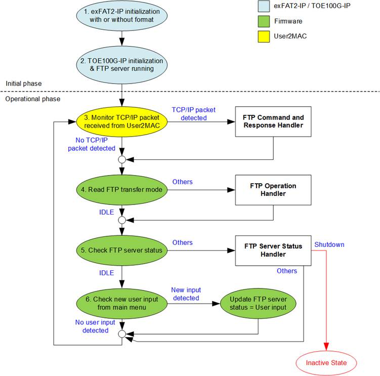
Figure 31 Firmware Operation Flow
1) The system starts by initializing the exFAT2-IP module, with or without formatting. During this phase, all necessary configurations are applied to enable SSD interaction through exFAT2-IP.
2) After completing the exFAT2-IP initialization, the TOE100G-IP module is initialized. This module handles data connections and must be fully configured before the system enters the operational phase. Once completed, the system displays test menu and the FTP server is ready to accept connections.
3) During the operational phase, the system monitors incoming packets from the User2MAC module.
· If no packets are received, the system advances to the next step.
· If packets are received, the system executes the “FTP Command and Response Handler” function (detailed in Section 3.1). This function updates the FTP transfer mode from IDLE to the appropriate mode (e.g., STOR, RETR, or LIST) if a data transfer command is detected.
4) The system checks the FTP transfer mode.
· If the mode is IDLE, it advances to the next step.
· If not, the system executes the “FTP Operation Handler” function (detailed in Section 3.2). This function monitors the statuses of the exFAT2-IP and TOE100G-IP module to assess their operational states.
5) The system checks the FTP server status.
· If the status is IDLE, it proceeds to next step.
· If not, the system executes the “FTP Server Status Handler” function (detailed in Section 3.3). Based on the current FTP server status, the system performs the corresponding operation. If the server status is “Shutdown”, the system transitions to an Inactive state after completing the command.
6) The system checks for user input.
· If no input is detected, it returns to step 3 (packet monitoring).
· If input is received, the system updates the FTP server status from IDLE to the corresponding status based on the provided input. The available test menu options for user reference are as follows:
i) Display FTP Client Setting: View the current configuration of the FTP client.
ii) Change FTP Client Setting: Modify the FTP client settings as needed.
iii) Change Time Created by FTP: Update the timestamp associated with FTP upload operations.
iv) Monitor FTP Transfer: Track ongoing FTP data transfers in real time.
v) Display Disk Information: Access detailed information about the connected disk.
vi) Write File: Perform a Write file operation to the disk.
vii) Read File: Execute a Read file operation from the disk.
viii) Shutdown: Safely terminate the FTP server’s operation.
3.1 FTP Command and Response Handler
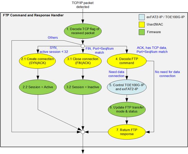
Figure 32 FTP Command and Response Handler Flow
The FTP Command and Response Handler function processes incoming TCP packets and decodes FTP commands. It manages FTP sessions and determining whether a data transfer is required. Below is a detailed explanation of the handling process:
1) After receiving a new packet from the UserRxMAC module, the system decodes the TCP flag to determine the appropriate action:
· If the TCP flag is SYN and the total number of sessions is less than 32, proceed to step 2.
· If the TCP flag is FIN, the session is still active, and the port and sequence numbers match the expected values, proceed to step 3.
· If the TCP flag is ACK, the session is still active, the port and sequence numbers match the expected values, and the TCP payload data size is not zero, proceed to step 4.
· Otherwise, exit the function.
2) Create a new connection by performing the following steps:
i) Generate a SYN|ACK packet and wait until a valid ACK packet without data is received.
ii) Update the session status from Inactive to Active.
3) Terminate the connection by performing the following steps.
i) Generate a FIN|ACK packet and wait until a valid ACK packet without data is received.
ii) Update the session status from Active to Inactive.
4) Decode the TCP payload to identify the FTP command type:
· Commands without data transfer: Proceed to step 7. Details for handling these commands are provided in Section 3.4.1.
· Commands requiring data transfer: Proceed to step 5.
5) Handle data transfer via the FTP data connection using TOE100G-IP and exFAT2-IP. The CPU configures the necessary parameters and monitor the operation status to confirm completion. Details for processing FTP commands requiring data transfer are described in Section 3.4.2.
6) The FTP transfer mode and status are updated based on the specific FTP command received.
7) Prepare the FTP response packet in TxRAM and configures UserTxMAC to transmit the FTP response.
3.2 FTP Operation Handler
The FTP Operation Handler focuses on monitoring and managing the progress of FTP commands that require data transfer. This section ensures efficient handling of commands such as STOR, RETR, and LIST, coordinating between the exFAT2-IP and TOE100G-IP modules for successful data transfer. Below is the step-by-step operation flow.
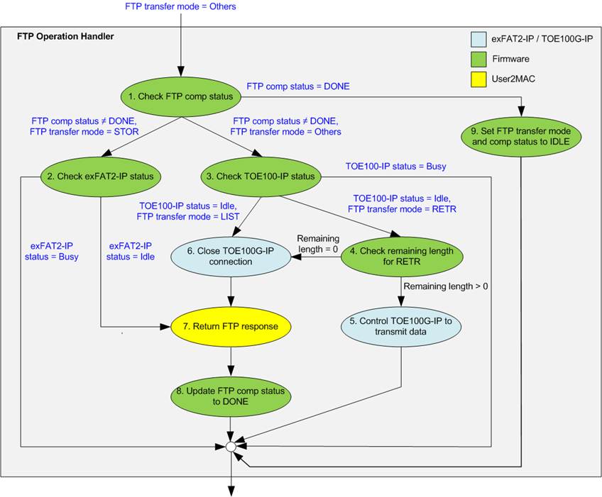
Figure 33 FTP Operation Handler Flow
1) Read the FTP completion status and transfer mode:
· If FTP completion status = DONE, proceed to step 9.
· If FTP completion status ≠ DONE and FTP transfer mode is STOR, proceed to step 2.
· Otherwise, proceed to step 3.
2) Monitor data transfer status for STOR command:
· If exFAT-IP status = busy, exit the function to allow other tasks to execute while waiting for the data transfer to complete.
· If exFAT-IP status = Idle, the STOR command data transfer is complete. Proceed to step 7.
3) Monitor data transfer status of TOE100G-IP for other commands:
· If TOE100G-IP status = busy, exit the function to allow other tasks to execute while waiting for the data transfer to complete.
· If TOE100G-IP status = Idle and FTP transfer mode = LIST, the LIST command is complete. Proceed to step 6.
· Otherwise, proceed to step 4.
4) Handle RETR command data transfer. If the transfer size exceeds 2 GB, a maximum data size per TOE100G-IP command in this system, multiple commands are required to complete the transfer. Check the remaining data transfer length.
· If remaining length = 0, proceed to step 6.
· Otherwise, proceed to step 5.
5) Configure TOE100G-IP registers to transmit data sourced from exFAT2-IP through the FTP data connection, then exit the function.
6) Configure TOE100G-IP registers to terminate the FTP data connection, then proceed to step 7.
7) Write the FTP response packet to TxRAM to indicate command completion, and configure UserTxMAC parameters to transmit the FTP response.
8) Set the FTP completion status to DONE to signal that the command is complete.
9) Update the FTP transfer mode and FTP completion status to IDLE, marking the system ready for the next operation.
3.3 FTP Server Status Handler
The FTP server status consists of eight distinct states, corresponding to the eight test menu options. The operational flow for each state is illustrated in Figure 34.
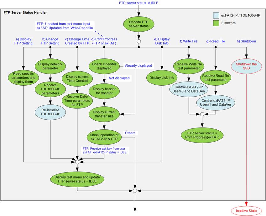
Figure 34 FTP Server Status Handler Flow
3.3.1 Display FTP Setting
This status operates to present the current parameters of TOE100G-IP, Time created by FTP, and FTP server information. The following steps are executed to display FTP client setting
1) Retrieve all network parameters from the firmware variables, including Window update threshold, Reverse packet enable, Source MAC address, Source IP address, Source port number, Target IP address, and Target port number. The Source parameters specify the local device’s configuration, while the Target parameters specify the configuration of the remote device.
2) Read the time created by FTP, which is used in the STOR command.
3) Retrieve the current FTP server information, including the FTP server IP address, username, and password.
4) Display the test menu and update the FTP server status to IDLE.
3.3.2 Change FTP Setting
This status allows modification of the TOE100G-IP parameters, such as the IP address and source port number. After the updated values are written to the TOE100G-IP registers, the CPU initiates a reset to reinitialize the TOE100G-IP with the new parameters. The initialization process is monitored via the busy flag to ensure completion. Note that this menu cannot be executed if an FTP client is actively transferring data. The steps to change the FTP client setting are as follows:
1) Display all current parameters on the console, as described in Section 3.3.1 (Display FTP Setting).
2) If the user chooses to use the default values, skip to the next step. Otherwise, display a menu to allow the user to set new values for all parameters. Each input is validated individually, and any invalid input will prevent that parameter from being updated.
3) Force a reset to the TOE100G-IP by setting TOE_RST_INTREG[0]=1b.
4) Write the updated parameters to the TOE100G-IP registers, such as TOE_SML_INTREG and TOE_DIP_INTREG.
5) De-assert the TOE100G-IP reset by setting TOE_RST_INTREG[0]=0b to begin the reinitialization process of the TOE100G-IP.
6) Monitor the TOE100G-IP busy flag (TOE_CMD_INTREG[0]) until the initialization process completes, indicated by the de-assertion of the busy flag (0b).
7) Display the test menu and update the FTP server status to IDLE.
Note: This command cannot be executed while the FTP transfer is in progress.
3.3.3 Change Time Created by FTP
This status allows the user to modify the Date/Time variable for FTP operations. The updated value is applied to the U0DATETIME_INTREG register during the execution of the STOR command. Note that this menu cannot be executed if an FTP client is actively transferring data. The following steps outline the process to change the time created by FTP:
1) Display the current Date/Time variable on the console.
2) Allow the user to either retain the current value or modify the parameters. If the user opts to change the parameters, the system will display a menu to set new values. The user inputs each parameter, which the system validates individually. Any invalid input will prevent the corresponding parameter for being updated.
3) Display the updated Date/Time variable on the console.
4) Display the test menu and update the FTP server status to IDLE.
3.3.4 Print Progress (FTP/exFAT)
This status is divided into two sub-modes:
· FTP mode, labeled as “Print Progress (FTP),” is updated when the user selects the “Monitor FTP Transfer” option from the test menu.
· exFAT mode, labeled as “Print Progress (exFAT),” is updated following finishing Write File (detailed in Section 3.3.6) or Read File status (detailed in Section 3.3.7).
The specific operations for each sub-mode are outlined below:
1) The CPU checks the first header flag to determine whether the header has been displayed. If the header has already been displayed, proceed to step 3. Otherwise, continue to step 2.
2) The appropriate header is displayed based on the sub-mode:
· In FTP mode: only the header for FTP transfer is displayed.
· In exFAT mode: headers for both FTP transfer and exFAT2-IP transfer are displayed.
3) The CPU checks U0/U1STS_INTREG[1] to detect errors. If the flag is set to 1b, it indicates an error on User#0 or User#1. The CPU retrieves error details from U0/U1ERRTYPE_INTREG and U0/U1NVMERRTYPE_INTREG, interprets the values, and displays a corresponding error message on the console.
4) The CPU monitors U1STS_INTREG[2] to detect verification failures during the Read File operation. If a failure occurs (1b), error details are displayed on the console at the first detection. Despite verification errors, the test operation continues until completion.
5) The CPU monitors U0/U1STS_INTREG[0] or TOE_CMD_INTREG[0] to determine whether data transfer is ongoing.
· If a transfer is detected, the CPU retrieves the current transfer size from U0/1CURTESTSIZEL/H_INTREG and displays the progress on the console every second.
· If no transfer is detected, the console displays a blinking dash (-) to indicate inactivity.
6) The CPU monitors U0/U1STS_INTREG[0] or TOE_CMD_INTREG[0] to determine if the transfer has been completed. Once complete:
i) The total transfer size is retrieved from U0/U1CURTESTSIZEL/H_INTREG.
ii) The timer value is used to calculate the total time usage and average transfer speed.
iii) These results are displayed on the console, summarized the transfer performance. Additionally, the number of stored files on the disk is updated by reading the value from DFNUM_INTREG.
7) The FTP server status is updated based on the conditions of the respective sub-modes:
· FTP mode: the status changes to IDLE if the “exit” key is detected from user input.
· exFAT mode: the status changes in the following cases:
· When the exFAT2-IP status is IDLE, the FTP transfer mode is not IDLE, and the “exit” key is detected from user input.
· When both the exFAT2-IP status and the FTP transfer mode are IDLE.
If any of these conditions are met, the test menu is displayed, and the FTP server status is updated to IDLE. Otherwise, the current FTP server status remains unchanged.
3.3.5 Display Disk Info
This status provides information about the SSD connected to the FTP server. The displayed details include the current file size, retrieved from U0FSIZE_INTREG, the maximum number of files the disk can hold, obtained from TOTALFCAP_INTREG, and the total number of files currently stored on the disk, accessed through DFNUM_INTREG. Once the SSD information is displayed, the system shows the test menu and update the FTP server status to IDLE.
3.3.6 Write File
The operation for the Write file command is outlined below:
1) Call the “check_exfatbusy” function to verify the busy status of User#0. If the user is busy, the command is cancelled.
2) Prompt the user to configure the created date and time for the new file or use the current value. Compute the result and set it to U0DATETIME_INTREG.
3) Display the latest write file name and prompt the user to either use the next sequential value to create new files or specify a custom file name to overwrite old files with new data. Validate the input and configure the selected name to U0FNAME_INTREG.
4) Request additional inputs from the user, including the number of files and the test pattern. Validate these inputs and compute the total transfer size for displaying on the console.
5) Configure the validated inputs into the corresponding registers, including U0FNAME_INTREG, U0FLEN_INTREG, U0CMD_INTREG, DATAGENPATTSEL_INTREG, and DATAGENEN_INTREG. Following this, the IP initiates the operation.
6) Update the FTP server status to “Print Progress (exFAT)”.
3.3.7 Read File
The operation for the Read Fiel command is outlined below:
1) Call the “check_exfatbusy” function to verify the busy status of User#1. If the user is busy, the command is cancelled.
2) Read the value from DFNUM_INTREG to determine the number of available files on the SSD. Display this value to inform the user of the valid range for specifying the first file name.
3) Prompt the user to specify the file name, validate its value, and configure the validated name to U1FNAME_INTREG.
4) Request additional inputs from the user, including the number of files and test pattern. Validate these inputs and compute the total transfer size for displaying on the console.
5) Configure the validated inputs into the corresponding registers, including U1FNAME_INTREG, U1FLEN_INTREG, U1CMD_INTREG, DATAVERPATTSEL_INTREG, and DATAVEREN_INTREG. Following this, the IP initiates the operation.
6) Update FTP server status to “Print Progress (exFAT)”.
3.3.8 Shutdown
This menu cannot be executed if an FTP client is actively transferring data. The steps for the Shutdown command are as follows.
1) Prompt the user to confirm the Shutdown operation. The user must enter the required keys to either proceed with or cancel the shutdown.
2) Set bit[8] and bits[2:0] of U0CMD_INTREG to issue the Shutdown command. Once initiated, exFAT2-IP sets the busy status (U0STS_INTREG[0]) to 1b.
3) Monitor the value of U0STS_INTREG[1:0] to determine command completion or error detection.
· If bit[0] is set to 0b, the command has successfully completed. Proceed to the next step.
· If bit[1] is set to 1b, an error has been detected on User#0. Retrieve the error details from U0ERRTYPE_INTREG and U0NVMERRTYPE_INTREG, interpret the values, and display a corresponding error message on the console.
4) Once the command is successfully completed, a message is displayed indicating that the SSD is now inactive. At this point, the user can no longer send requests to exFAT2-IP, and the FTP client cannot communicate with the FTP server. To resume testing, the user must power off and then power on the system.
3.4 FTP Command Types
FTP commands are classified into two categories: commands that do not require a data connection and commands that require a data connection. Commands in the first category operate exclusively through the control connection, while those in the second category utilize both the control connection and the data connection for transferring data. The following section details the steps for processing commands that do not require the data connection.
3.4.1 FTP Commands without Data Connection
The following steps outline the process for handling FTP commands that do not require a data connection.
1) Generate the FTP response packet and store it in the transmit temporary buffer, based on the command type. This demo implements mandatory FTP commands for compatibility with common FTP client applications, such as FileZilla. A list of implemented commands is provided in Table 2.
2) Call the function to generate the packet header and calculate the checksum for the FTP response.
3) Copy the FTP response packet from the transmit temporary buffer to TxRAM (txbuff_ch) and set the total transfer length in TXEMAC_LEN_INTREG to initiate transmission.
4) Monitor the busy flag in UserTxMAC (TXEMAC_LEN_INTREG), and proceed once the flag is cleared to 0b.
Table 2 Implemented FTP Responses for FTP Commands without Data Connection
|
FTP command |
Description |
Implemented FTP Response |
|
USER |
Authentication username |
331 User is correct. Password is required. |
|
530 Login is incorrect. |
||
|
PASS |
Authentication password |
230 Logged in. |
|
530 Login is incorrect. |
||
|
PWD |
Print working directory |
257 "PATHNAME" is the current directory. |
|
TYPE |
Set the transfer mode |
200 Type set to I. |
|
PASV |
Enter passive mode |
227 Enter Passive mode (h1,h2,h3,h4,p1,p2; h1-h4: IP address, p1-p2: Port number). |
|
CWD |
Change working directory |
250 Requested file action Okay. |
|
DELE |
Delete file |
202 Not implemented. |
|
QUIT |
Log out session |
221 Bye. |
For FTP commands not listed in the table, such as AUTH, PORT, SYST, and FEAT, the response returned is 500: Syntax error.
The PASV command is generally issued by the client to initiate the passive mode before executing FTP commands that require a data connection, such as LIST, RETR, and STOR. Detailed descriptions of these commands will be provided in the next section.
Note: The DELE command is not implemented in the reference design, so users cannot delete files from the server’s storage.
3.4.2 FTP Command with Data Connection
FTP commands that require a data connection are summarized in Table 3. These commands involve transferring files or retrieving directory listings and differ from FTP commands without data connections as they necessitate an active data connection. The initial processing steps for these commands follow the procedure described in steps (1) – (4) of Section 3.4.1.
When an FTP command requiring a data connection is received, the system selects the appropriate user channel to handle the transfer.
· The STOR command uses User#0 to transfer data from the FTP client (TOE100G-IP) to the server’s storage (exFAT2-IP).
· The LIST and RETR commands use User#1 to retrieve directory listings and file data, respectively.
If the selected user channel is busy, such as during an operation initiated from the main menu, the system responds with a “425 Cannot open data connection”, cancelling the current FTP command.
Table 3 FTP Responses for FTP Command with Data Connection
|
FTP command |
Description |
Implemented FTP Response |
|
LIST |
Return the file list in the current directory. |
125 Open data connection 226 Transfer complete 425 Cannot open data connection |
|
STOR |
Accept data and store it as a file on the server site. |
|
|
RETR |
Retrieve a copy of file. |
Detailed descriptions of each FTP command are provided
below. Before initiating these commands, the PASV command (described earlier)
must be executed to establish a data connection.
LIST
The LIST command is used to retrieve and return a list of files in the current directory. The CPU firmware generates this file list, which is transmitted through the FTP data connection controlled by TOE100G-IP. The steps for executing the LIST command are as follows.
1) Read the number of files stored on the device from DFNUM_INTREG or DFNUMCUR_INTREG (if a Write file operation is in progress).
2) Monitor the connection status of TOE100G-IP by checking TOEIP_STS_INTREG[1]=1b to confirm that the data connection has been successfully established.
3) Call the function to prepare the FTP response 125 (Open data connection), store it in TxRAM, and start packet transmission.
4) Configure TOE100G-IP parameters for transmitting file information by setting the following parameters: Transmit packet size (TOE_PKL_INTREG), Total transmit data length (TOE_TDL_INTREG), and Command to start sending data (TOE_CMD_ INTREG=Send).
5) Prepare the file information and write it to TOE_TXDATA_INTREG.
· For files already written to the SSD, retrieve the date and time from U1FINFO_INTREG to reflect the last modified or created timestamp.
· For files currently being written to the SSD, use U0DATETIME_INTREG.
The file information is then transmitted through the data connection using TOE100G-IP.
6) Monitor the TOE100G-IP busy flag by checking TOE_CMD_INTREG[0]=0b to confirm that data transmission is complete.
7) Send a Close command to TOE100G-IP (TOE_CMD_INTREG=Close) to terminate the FTP data connection.
8) Monitor the TOE100G-IP busy flag by checking TOE_CMD_INTREG[0]=0b to confirm that the connection has been terminated.
9) Call the function to prepare the FTP response 226 (Transfer complete), store it in TxRAM, and start packet transmission.
STOR
The STOR command is used to store a file received from the FTP client onto the SSD. The following steps outline the process.
1) Convert the file name received from the FTP client (in ASCII format) into an unsigned integer.
2) Configure the exFAT2-IP parameters to store the data received from the FTP client onto the SSD. The parameters include File name (U0FNAME_INTREG), Date/Time (U0DATETIME_INTREG), and Command (U0CMD_INTREG = Write file).
Note: The system supports transferring one file at a time, with the number of files fixed to 1. The Date/Time used will be a dedicated FTP date/time variable, separate from the one used in the Write File operation.
3) Monitor the connection status of TOE100G-IP by checking TOEIP_STS_INTREG[1]=1b to confirm that the data connection has been established.
4) Call the function to prepare the FTP response 125 (Open data connection), store it in TxRAM, and start packet transmission.
5) Monitor the busy flag of exFAT2-IP (U0STS_INTREG=0b) to confirm that the data transmission is complete.
6) Monitor the connection status of TOE100G-IP by checking TOEIP_STS_INTREG [1]=0b to confirm that the data connection has been terminated.
7) Call the function
to prepare the FTP response 226 (Transfer complete), store it in TxRAM, and
start packet transmission.
RETR
The RETR command is used to retrieve a file from the SSD and transfer it to the FTP client. The following steps outline the process.
1) Convert the file name received from the FTP client (in ASCII format) into an unsigned integer.
2) Configure the exFAT2-IP parameters to read the file data from the SSD by setting File name (U1FNAME_INTREG) and Command (U1CMD_INTREG=Read file).
Note: The system supports transferring one file at a time, with the number of files fixed to 1. Registers configured for User#1 (U<1>Register_Name) can be accessed using the address offset (U<0>Register_Name + USEROFFSET_INT).
3) Monitor the connection status of TOE100G-IP by checking TOE_STS_INTREG[1]=1b to confirm that the data connection has been established.
4) Call the function to prepare the FTP response 125 (Open data connection), store it in TxRAM, and start packet transmission.
5) Configure the TOE100G-IP parameters to transfer data from the SSD by setting Transmit packet size (TOE_PKL_INTREG), Total transmit data length (TOE_TDL_INTREG), and Command to start sending data (TOE_CMD_INTREG=Send).
6) Monitor the TOE100G-IP busy flag (TOE_CMD_INTREG[0]=0b) until the data transmission is complete. If the file size exceeds 2 GB, the process repeats step 5 until the total transferred size matches the file size specified by exFAT2-IP.
Note: The maximum file size on the SSD is 32 GB, while this design limits the TOE100G-IP transfer size to 2 GB per operation. If a file is larger than 2 GB, TOE100G-IP will repeatedly process data until the entire file is transferred as specified by exFAT2-IP.
7) Follow steps 7 – 9 of the LIST command to terminate the data connection and send the FTP response 226 (Transfer complete).
3.5 Function List in Test Firmware
3.5.1 Function for exFAT2-IP
This section describes the function list to execute exFAT2-IP operations.
|
void change_ftime(unsigned int trn_mode, unsigned int *DateTime) |
|
|
Parameters |
trn_mode: Transfer mode (MODE_EXFAT: For exFAT2-IP transfer, MODE_FTP: For FTP client transfer) DateTime: Pointer to the created date and time parameters. |
|
Return value |
None |
|
Description |
Print the current created date and time by calling the ‘show_ftime’ function. Afterward, prompt the user to either keep the existing value or enter a new one. If a new value is provided, it is validated before updating U0DATETIME_INTREG and the global parameter (DateTime). |
|
int check_exfatbusy(unsigned int cmd) |
|
|
Parameters |
cmd: Command to check write or read interface. |
|
Return value |
0: User is available. 1: User is busy. |
|
Description |
Check whether the write or read interface is busy based on the provided command. If the interface is busy, a message is displayed on the console. |
|
int format_fat(void) |
|
|
Parameters |
None |
|
Return value |
0: Command completed or cancelled by the user. -1: Invalid input received or an error occurred. |
|
Description |
Execute the (Secure) Format command by following these steps. 1) Call ‘change_ftime’ to set the created date and time. 2) Read disk capacity from NVMLBASIZEH/L_INTREG and calculate the supported file size. 3) Set the file size to U0FSIZE_INTREG based on user input. 4) Set U0CMD_INTREG to Format/Secure Format command and wait for the operation to complete. 5) Display disk information by calling the ‘show_diskinfo’ function. |
|
void get_cursize(unsigned int user, unsigned long long* cursize) |
|
|
Parameters |
user: User index (0 or 1). cursize: Pointer to store the current transfer size |
|
Return value |
None |
|
Description |
Read U<i>CURTESTSIZEL/H_INTREG (‘i’ represents the user index), determine the current transfer size, and update the result to ‘cursize’ parameter. |
|
int get_param(userin_struct* userin, unsigned int user) |
|
|
Parameters |
userin: Pointer to store a set of test parameters input by the user, including the command, file name, number of files, and test pattern. user: User index (0 or 1). |
|
Return value |
0: Valid input received. -1: Invalid input received. |
|
Description |
Receive test parameters from the user via the console and validate their values. If any input is invalid, the function returns -1. Otherwise, the values are stored in userin. |
|
void monitor_transfer(unsigned int trn_mode) |
|
|
Parameters |
trn_mode: Transfer mode (MODE_EXFAT: For exFAT2-IP transfer, MODE_FTP: For FTP client transfer) |
|
Return value |
None |
|
Description |
This function is described in Section 3.3.4. |
|
void show_compfile(unsigned int firstfile, unsigned int lastfile) |
|
|
Parameters |
firstfile: The first file name of the operation. lastfile: The last file name of the operation. |
|
Return value |
None |
|
Description |
Display the first file name and the last file name of the operation on the console. |
|
void show_diskinfo(void) |
|
|
Parameters |
None |
|
Return value |
None |
|
Description |
Retrieve and displays SSD information, including File size (retrieved via calling ‘show_fsize’ function), Maximum number of files the SSD can hold (TotalFCap variable in firmware), and Total number of available files (DFnum variable on firmware). |
|
void show_error(unsigned int user) |
|
|
Parameters |
user: User index (0 or 1). |
|
Return value |
None |
|
Description |
Read error details from U<i>ERRTYPE_INTREG and U<i>NVMERRTYPE_INTREG (where ‘i’ is the user index), interpret the error type, and display the result on the console. |
|
void show_fsize(void) |
|
|
Parameters |
None |
|
Return value |
None |
|
Description |
Read the file size parameter (DFsize variable in firmware), decode it to MB or GB units, and display the result on the console. |
|
void show_ftime(unsigned int trn_mode, unsigned int time_input) |
|
|
Parameters |
trn_mode: Transfer mode (MODE_EXFAT: For exFAT2-IP transfer, MODE_FTP: For FTP client transfer) time_input: Time and date input |
|
Return value |
None |
|
Description |
Decode ‘trn_mode’ to identify the source of file creator and display it. Then, read ‘time_input’, decode it into date, month, year, hour, minute, and second, and display the result on the console. |
|
void show_result(unsigned int trn_mode, unsigned int user, userin_struct* userin, unsigned int timeuseh, unsigned int timeusel) |
|
|
Parameters |
trn_mode: Transfer mode (MODE_EXFAT: For exFAT2-IP transfer, MODE_FTP: For FTP client transfer) user: User index (0 or 1). userin: Pointer to store a set of test parameters input by the user, including the command, file name, number of files, and test pattern. timeuseh: Upper 32-bit value of the timer. timeusel: Lower 32-bit value of the timer. |
|
Return value |
None |
|
Description |
Execute the following steps. 1) Update the total transfer size by calling ‘get_cursize’ function and display the result on the console using the ‘show_size’ function. 2) Display the total time usage using the ‘show_time’ function, calculate the transfer performance, and print the result on the console. 3) Calculate the last file name and call ‘show_dir’ to display the first and last file names along with their directory names. If an abort was requested, the actual transfer size is also displayed. 4) Update the number of available files on the disk by reading ‘DFNUM_INTREG’ and display the result on the console. |
|
void show_size(unsigned long long size_input) |
|
|
Parameters |
size_input: Data size in bytes. |
|
Return value |
None |
|
Description |
Convert and displays the input data size in MB or GB units. |
|
void show_testpin(void) |
|
|
Parameters |
None |
|
Return value |
None |
|
Description |
Read values from U0-1TESTPINL/H_INTREG and NVMU0-1TESTPINL/H, and display the results on the console. |
|
void show_time(unsigned int timesueh, unsigned int timesuel) |
|
|
Parameters |
timeuseh: Upper 32-bit value of the timer. timeusel: Lower 32-bit value of the timer. |
|
Return value |
None |
|
Description |
Calculate the total time usage from ‘timesueh’ and ‘timesuel’, and display the result on the console in usec, msec, or sec. |
|
void show_vererr(void) |
|
|
Parameters |
None |
|
Return value |
None |
|
Description |
Read the error details from verification-related registers and display them on the console, including U1FAILFNAME_INTREG (error file name), U1FAILADDRL/H_INTREG (error address), U1EXPPATW0-15_INTREG (expected value), and U1RDPATW0-15_INTREG (read value). |
|
int shutdown_dev(void) |
|
|
Parameters |
None |
|
Return value |
0: Shutdown command successfully completed. -1: Shutdown command cancelled by user or an error occurred. |
|
Description |
Execute the Shutdown command as outlined in Section 3.3.7. |
|
void update_diskparam(void) |
|
|
Parameters |
None |
|
Return value |
None |
|
Description |
Read the following registers and updates the corresponding internal parameters: TOTALFCAP_INTREG -> TotalFCap (maximum file capacity). DFSIZE_INTREG -> DFsize (disk file size). DFNUM_INTREG or DFNUMCUR_INTREG -> DFnum or DFnumCur (total or current number of stored files). |
|
int wrrd_file(unsigned int user_cmd) |
|
|
Parameters |
user_cmd: User command (CMD_WRITE, CMD_READ) |
|
Return value |
0: Operation successful. -1: Invalid input received or an error occurred. |
|
Description |
Execute Write or Read File operations as outlined in Section 3.3.6. |
3.5.2 Function for TOE100G-IP
The functions in this section are used to control TOE100G-IP.
|
void exec_port(unsigned int port_ctl, unsigned int mode_active) |
|
|
Parameters |
port_ctl: 1-Open port, 0-Close port. mode_active: 1-Active open/close, 0-Passive open/close. |
|
Return value |
None |
|
Description |
For active mode, write to TOE_CMD_INTREG to open or close the connection. After executing the command, it calls the ‘read_conon’ function to monitor the connection status until it changes from ON to OFF or OFF to ON, depending on the ‘port_ctl’ value. |
|
void init_toe_param(void) |
|
|
Parameters |
None |
|
Return value |
None |
|
Description |
Initializes TOE100G-IP parameters by performing the following steps: 1) Call ‘show_param’ function to display the current network parameters. 2) If the user chooses to use the current values, skip to step 3. Otherwise, call ‘input_param’ function to receive new parameters from the user. 3) Force a reset of TOE100G-IP by setting TOE_RST_INTREG[0]=1b. 4) Write network parameters to TOE100G-IP register. 5) De-assert the TOE100G-IP reset by setting TOE_RST_INTREG[0]=0b to begin the initialization process. 6) After de-asserting the reset, wait until the TOE100G-IP busy flag is de-asserted to 0b. 7) Set the header value and header enable for packet filtering in UserRxMAC. 8) Set the default value for the FTP response parameter. |
|
int input_param(void) |
|
|
Parameters |
None |
|
Return value |
0: Valid input. -1: Invalid input. |
|
Description |
Receive network parameters from the user, including Reverse packet enable, Window threshold, FPGA MAC address, FPGA IP address, FPGA port number, Target IP address, and Target port number. Each parameter is validated individually. If an input is valid, it is updated. If invalid, the parameter remains unchanged. After all parameters are received, the function calls ‘show_param’ function to display the updated settings. |
|
void read_conon(unsigned int* status) |
|
|
Parameters |
status: Pointer to store TCP connection status |
|
Return value |
None |
|
Description |
Read bit[1] of TOE_STS_INTREG to retrieve the current TCP connection status and update the value in the pointer. |
|
void show_param(void) |
|
|
Parameters |
None |
|
Return value |
None |
|
Description |
Perform the following steps: 1) Read all network parameters from firmware variables, including Window update threshold, Reverse packet enable, Source (FPGA) MAC address, Source (FPGA) IP address, Source (FPGA) port number, Target IP address, and Target port number. 2) Display each parameter on the console. |
|
void wait_ethlink(void) |
|
|
Parameters |
None |
|
Return value |
None |
|
Description |
Read USER_RST_INTREG[16] and wait until the Ethernet connection is established. |
3.5.3 Function for FTP operation
The functions in this section are used to control FTP operations.
|
void cal_checksum(unsigned int byte_len, unsigned char *buf, unsigned int* csum_val) |
|
|
Parameters |
bytel_len: Number of bytes in the input data for checksum calculation. buf: Pointer to the packet data to calculate the checksum. csum_val: Pointer to store the calculated checksum value |
|
Return value |
None |
|
Description |
Calculate the 16-bit checksum of the data in the buffer and update the result in ‘csum_val’. |
|
void decode_fname(unsigned int* filename) |
|
|
Parameters |
filename: Pointer to store the decoded file name. |
|
Return value |
None |
|
Description |
Convert the file name from the received ASCII-encoded packet into a numerical value and update to ‘filename’. |
|
void ftp_op_handle(void) |
|
|
Parameters |
None |
|
Return value |
None |
|
Description |
Handle FTP operations as described in Section 3.2. |
|
void ftp_rxpac_dec(void) |
|
|
Parameters |
None |
|
Return value |
None |
|
Description |
Handle packet reception and decoding for FTP commands as described in Section 3.1. |
|
int read_rxpacket(void) |
|
|
Parameters |
None |
|
Return value |
0: No packet received. 1: Packet received. |
|
Description |
Check for a new received packet from UserRxMAC. If a new packet is detected, it is copied to the receive temporary buffer for further processing. |
|
void send_list(userin_struct* userin) |
|
|
Parameters |
userin: Pointer to store a set of test parameters input by the user, including the command, file name, number of files, and test pattern. |
|
Return value |
None |
|
Description |
Generate and transmit the file list, including the last modified date and time, for the LIST command, as described in Section 3.4.2 (LIST Command). |
|
void send_resp(unsigned int flag, unsigned int ftp_response) |
|
|
Parameters |
flag: TCP flag in the received packet. ftp_response: FTP response message to be sent. |
|
Return value |
None |
|
Description |
Send the FTP response using UserTxMAC. |
|
void set_tx_csum(void) |
|
|
Parameters |
None |
|
Return value |
None |
|
Description |
Assign the checksum to header of transmitted packet. |
|
void set_tx_header(unsigned int flag, unsigned int data_len) |
|
|
Parameters |
flag: TCP Flag for the transmitted packet. data_len: Total length of the transmitted data in bytes. |
|
Return value |
None |
|
Description |
Set the packet header for the transmitted packet, including the Ethernet header, IP header, and TCP header. |
|
void show_testmenu(void) |
|
|
Parameters |
None |
|
Return value |
None |
|
Description |
Display the list of test menu options on the console. |
|
void take_ftp_resp(void) |
|
|
Parameters |
None |
|
Return value |
None |
|
Description |
Process FTP commands listed in Table 2 and Table 3 by generating the FTP response and managing the data connection, as described in Section 3.4.1 and 3.4.2. |
4 Revision History
|
Revision |
Date (D-M-Y) |
Description |
|
1.00 |
30-Jan-25 |
Initial version release |