NVMeTCP25G-IP on Alveo Demo Instruction
Rev1.0 21-Aug-23
2.1 Application Installation on Target system (PC)
2.2 Ethernet Interface Setting on Target system (PC)
2.3 Set up NVMe/TCP Target by PC
2.4 Remove NVMe/TCP Target by PC
3 NVMe/TCP Host by Alveo accelerator card
4.2.3 Mixed Write/Read command
1 Overview
This guide provides instructions for running the NVMeTCP25G-IP demo on an Alveo accelerator card that includes four NVMeTCP25G-IPs, enabling the NVMe/TCP Host to access up to four NVMe SSDs installed to the NVMe/TCP Targets via a 25G Ethernet connection using NVMe/TCP protocol. To set up the NVMe/TCP Target system for this demo, a PC running Ubuntu 20.04.1 OS with an integrating NVMe SSD is used. By executing the demo, users can swrite and read data with each NVMe SSD on the Target system using each NVMe/TCP Host across 25G Ethernet at very high-speed rates. The user can control the parameters and test operation through the FPGA console.
In Topic 2 of this guide, the steps to set up the NVMe SSD inside the PC as an NVMe/TCP Target are outlined, as well as the steps to remove the NVMe/TCP Target from the system and return the SSD to an NVMe SSD. Topic 3 describes the process to set up the NVMe/TCP Host using the Alveo accelerator card. Additionally, it shows how to download the NVMeTCP25G-IP demo to the card. Topic 4 provides an example of how to run the demo and displays the test results. For more detailed information on each topic, please refer to the corresponding section below.
2 NVMe/TCP Target by PC
This topic describes the commands on Ubuntu 20.04.1 OS to set up the Target system for NVMeTCP25G-IP demo.
2.1 Application Installation on Target system (PC)
Before running NVMeTCP25G-IP demo, some applications need to be installed on the PC that is applied to be the NVMe/TCP Target system. These applications require to install once. After that, the installation is not necessary.
1) Ethtool is applied to tune the performance of the network card. Use following command to install ethtools.

2) NVMe Command Line Interface (NVMe-CLI) is applied to manage NVMe SSDs in Linux OS. Use following command to install NVMe-CLI.

2.2 Ethernet Interface Setting on Target system (PC)
For optimal performance when running the demo, it is recommended to configure a 25 Gb Ethernet network card using the following commands. Please open a new terminal to begin configuring the Ethernet interface.
1) To list the logical name of 25G Ethernet port on Linux terminal, use following command.

Figure 2‑1 shows the results when running the command. “enp1s0f0” is the 25Gb Ethernet interface connected to the NVMe/TCP host.
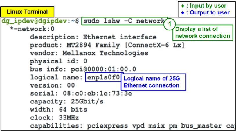
Figure 2‑1 Display logical name of 25G Ethernet connection
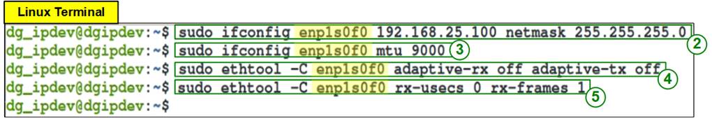
Figure 2‑2 IP address and Ethernet interface setting
2) Use command “ifconfig <interface> <ipaddr_value> netmask <netmask_value>” to set Target IP address and Subnet mask to the desired port of the Ethernet card.
a) Desired (interface) port of Ethernet card = “enp1s0f0”.
b) This example assigns one Target IP address to each 25G Ethernet connection for each NVMe/TCP Target access. Therefore, four IP addresses are applied to set up four NVMe/TCP Targets. The example of four Target IP addresses are as follows.
· Set IP address = 192.168.25.100, Subnet mask = 255.255.255.0 for Target#0
· Set IP address = 192.168.25.101, Subnet mask = 255.255.255.0 for Target#1
· Set IP address = 192.168.25.102, Subnet mask = 255.255.255.0 for Target#2
· Set IP address = 192.168.25.103, Subnet mask = 255.255.255.0 for Target#3

3) Use command “ifconfig <interface > mtu <mtu_value>” to set maximum transfer unit (mtu) over TCP/IP. Set mtu_value = 9000 to support jumbo frame packet.

4) Turn off Rx and Tx latency improvement algorithm by using command “sudo ethtool -C <interface> adaptive-rx off adaptive-tx off”.


2.3 Set up NVMe/TCP Target by PC
This topic describes how to configure the SSD that is plugged in to the PC to be NVMe/TCP target after finishing 25G Ethernet network setting, as shown in Figure 2‑3.
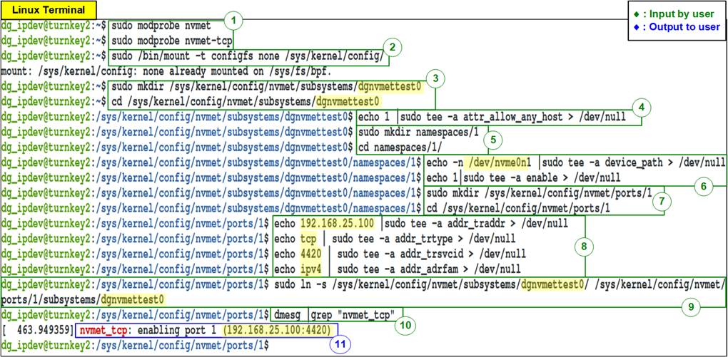
Figure 2‑3 Target setting
1) Load the Target module by using following command.

2) Mount the kernel user configuration filesystem by using following command.

3) Create the Target subsystem and define NVMe Qualified Name (NQN). NQN setting in this step must be matched to TrgNQN setting to the NVMeTCP25G-IP. For example, the name is “dgnvmettest0” for the first Target. After that, change directory to the subsystem directory by following command.

Note: Though TrgNQN value on NVMeTCP25G-IP supports up to 256 characters, the demo system allows user to input the name up to 16 characters for simply setting. Therefore, NQN length set on this step must not be more than 16 characters.
4) Set attribute to allow every host access with the created Target subsystem by using following command.

Note: Using “attr_allow_any_host” is the permission for testing only. In the real system, it is recommended to lock the permission by Host NQN.
5) Create a subsystem namespace and change directory to the new directory by using following command.

6) Set a local NVMe SSD installed in PC to the created namespace. After that, enable the namespace by using following command.

Note: The example of NVMe SSD installed in PC is “nvme0n1”. The name may be different when changing the test environments.
7) Create an NVMe target port to export the created subsystem and change into its directory path as follows.

8) Configure Ethernet parameters of the created target port including
a) IP address = 192.168.25.100
b) Transport type = “tcp”
c) Port number = 4420
d) Address family = “ipv4”
Note: IP address value corresponds to the IP of Ethernet card port in Topic 2.2 (Ethernet Interface Setting on Target system (PC).
9) Create a soft link pointed to the Target subsystem from the created port by using following command.

Note: The Target NQN must be corresponded to the previous steps (step 3).
10) Confirm the success of Target setting by reading debug message from following command.

11) If the target is set successfully, the message including Target IP address and port number are printed, as shown in Figure 2‑4.
![]()
Figure 2‑4 NVMe/TCP target setup success message
2.4 Remove NVMe/TCP Target by PC
This topic describes how to remove an SSD from NVMe/TCP Target after finishing testing, as shown in Figure 2‑5.
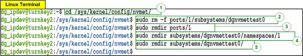
Figure 2‑5 Remove NVMe/TCP Target
1) Change directory to nvmet by following command.

2) Remove the target subsystem by following command.

3) Remove ports directory by following command.

4) Remove namespace directory by following command.

5) Remove subsystems directory by following command.

3 NVMe/TCP Host by Alveo accelerator card
This topic describes the procedures to set up NVMe/TCP Host system using the Alveo accelerator card, which integrates with NVMeTCP25G-IP. The Alveo card comes with a 100G Ethernet connection which can be split into four 25G Ethernet connections. As a result, the NVMe/TCP Host system powered by the Alveo card can transfer data to four NVMe/TCP Targets simultaneously, by incorporating four NVMeTCP25G-IPs.
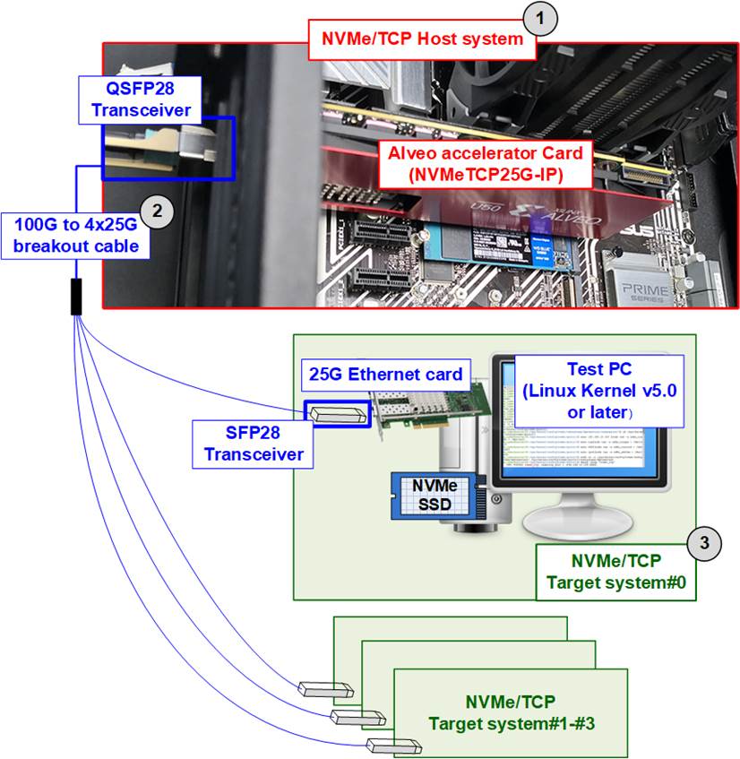
Figure 3‑1 Test environment for running the demo
Figure 3‑1 shows the test environment when connecting NVMe/TCP Host system to four NVMe/TCP Target systems which are set up by using PC installing Linux kernel version 5.0 or later and NVMe SSD. The test environment is listed as follows.
1) Alveo accelerator card with accelerator system for Alveo card.
· Alveo Accelerator card: U50 card
· Accelerator system for Alveo card: TKAS-D2101 with Ubuntu 20.04 LTS Server OS.
https://dgway.com/AcceleratorCards.html
2) 100G to 4x25G breakout cable
· QSFP28 Transceiver: AMQ28-SR4-M1
https://www.sfpcables.com/100gb-s-qsfp28-sr4-optical-transceiver-module-1499
· SFP28 Transceiver: AZS85-S28-M1 (4 sets for four 25G Ethernet connections)
https://www.sfpcables.com/25gb-s-sfp28-sr-transceiver-850nm-up-to-100m-2866
· MTP to 4xLC Fiber cable: OM4-MTP-8LC-1M
https://www.fs.com/products/68047.html
3) NVMe/TCP Target systems
· Four NVMe SSDs integrated to 1-4 PCs
· Install Linux kernel version 5.0 or later
· 25G Ethernet Card plugged into each PC: Nvidia MCX631102AC-ADAT
Follow the steps below to run the NVMeTCP25G-IP demo on the Alveo card.
Note: If this is the first time that Alveo accelerator card is plugged-in to the Accelerator system, please follows the installation steps recommended by Xilinx, provided as below.
https://docs.xilinx.com/r/en-US/ug1301-getting-started-guide-alveo-accelerator-cards
1) Detect Accelerator card which connects on the Accelerator system to get the Card BDF ID by using following command.

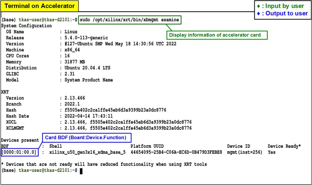
Figure 3‑2 Examine Accelerator card
2) Enable the host memory to reserve the memory for the target Alveo platform by using the following command with the “card_BDF” from the previous step.

For more information about Host Memory Access of Xilinx Accelerator platform can be found on the following Xilinx site.
https://xilinx.github.io/XRT/master/html/hm.html
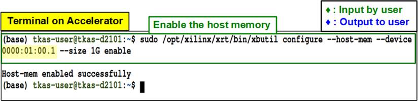
Figure 3‑3 Enable the host memory through XRT
3) Program the configuration file (xclbin) to Accelerator card, as shown in Figure 3‑4.
i) Open the terminal and change the directory where the xclbin file is located.
ii) Program the configuration file (xclbin) through PCIe by the following command along with the “card_BDF” and the xclbin file.
Note: The configuration file of this demo is “NVMeTCP25DMATest.xclbin” which is pre-built and ready to run in this system environment.

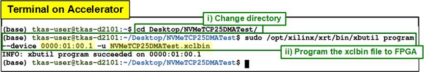
Figure 3‑4 Program the configuration file to the Accelerator card
4) Run the demo application which is “nvmetcp25_mul_dma_exe” on Accelerator system, as shown in Figure 3‑5.
i) On the same terminal after running the step 3, export the XRT (Xilinx) environment by using following command

ii) Run the following command to launch the demo application.

Note: “nvmetcp25_mul_dma_exe” is pre-built application that is stored in the “bin” directory. The “bin” directory is located in the same directory as the configuration file (NVMeTCP25DMATest.xclbin).
iii) After executing the demo application, the welcome message is displayed.
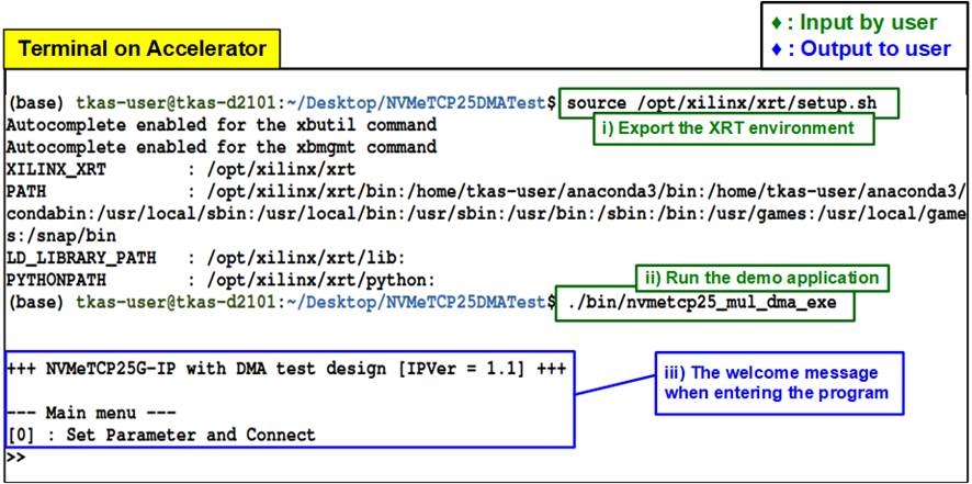
Figure 3‑5 Run the demo application after programming configuration file
4 Test operation
After the Alveo accelerator card is configured by NVMeTCP25G-IP demo successfully, the menu [0] (Set Parameter and Connect) to start connecting to the NVMe/TCP Target system is displayed. User confirms the Ethernet connection between the Alveo card and the Target before entering menu [0]. The details of each menu are described as follows.
4.1 Set Parameter and Connect
Select ‘0’ from the menu to set the IP parameters and connect to NVMe/TCP Target. After finishing the operation, the connection status with the NVMe/TCP Target is updated.
The Host system has four NVMeTCP25G-IPs, and each IP corresponds to one Host channel (0 - 3). Once the Host channel is selected, the current values of all parameters for that channel will be displayed. The user can choose to connect using the latest parameters by entering ‘x’ or modify the values by using other keys.
There are seven or eight parameters to set, each with a description provided below. Before use, the value of each parameter is verified. If the value is valid, it will be updated to the selected parameter. If not, the latest value will be applied without modification. After setting all parameters, the user can confirm the values by entering ‘y’ to start the connection establishment with the Target or re-modify the parameters with other keys.
1) Target NVMe Qualifed Name (NQN): Target NQN indicates which Target SSD that the Host wants to connect with. The input NQN must not exceed 16 characters, limited by the demo system.
2) Host MAC address: 48-bit hex value to be MAC address of the Host (NVMeTCP25G-IP). The input is 12 digits of hex value. Add “0x” as a prefix to input as hex value.
3) Host IP address: IP address of the Host. The input is a set of four decimal digits is separated by “.”. The valid range of each decimal digit is 0-255.
4) Host port number: Port number of the Host side including Admin port and IO port. Valid range of input is 0-65535.
5) Target MAC address mode: Press ‘y’ to change to Fixed MAC mode instead of ARP mode. Default mode is ARP mode (Get target MAC address from ARP).
6) Target MAC address (available only when using Fixed MAC mode): 48-bit hex value to be MAC address of the Target. The input is 12 digits of hex value. Add “0x” as a prefix to input as hex value.
7) Target IP address: IP address of the Target. The input is a set of four decimal digits is separated by “.”. The valid range of each decimal digit is 0-255.
The default values of the parameters for each Host channel are shown in Table 4‑1.
Table 4‑1 Default value of the parameters of each Host channel
|
Parameter name |
Host channel#0 |
Host channel#1 |
Host channel#2 |
Host channel#3 |
|
Host NQN |
dgnvmehtest0 |
dgnvmehtest1 |
dgnvmehtest2 |
dgnvmehtest3 |
|
Target NQN |
dgnvmettest0 |
dgnvmettest1 |
dgnvmettest2 |
dgnvmettest3 |
|
Host MAC address |
0x000102030405 |
0x000102030406 |
0x000102030407 |
0x000102030408 |
|
Host IP address |
192.168.25.44 |
192.168.25.45 |
192.168.25.46 |
192.168.25.47 |
|
Host Admin Port no. |
40000 |
|||
|
Host IO Port no. |
40001 |
|||
|
Target MAC address (Fixed MAC mode) |
0x101112131415 |
0x101112131416 |
0x101112131417 |
0x101112131418 |
|
Target IP address |
192.168.25.100 |
192.168.25.101 |
192.168.25.102 |
192.168.25.103 |
Once user confirms parameter values, the NVMeTCP25-IP registers are updated with all relevant parameters. After that, the selected Host initiates the connection creation process. After the connection is established, the current connection status is displayed again to update the connection status as shown in Figure 4‑1.
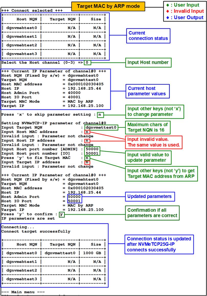
Figure 4‑1 Set Network Parameter result (ARP mode)
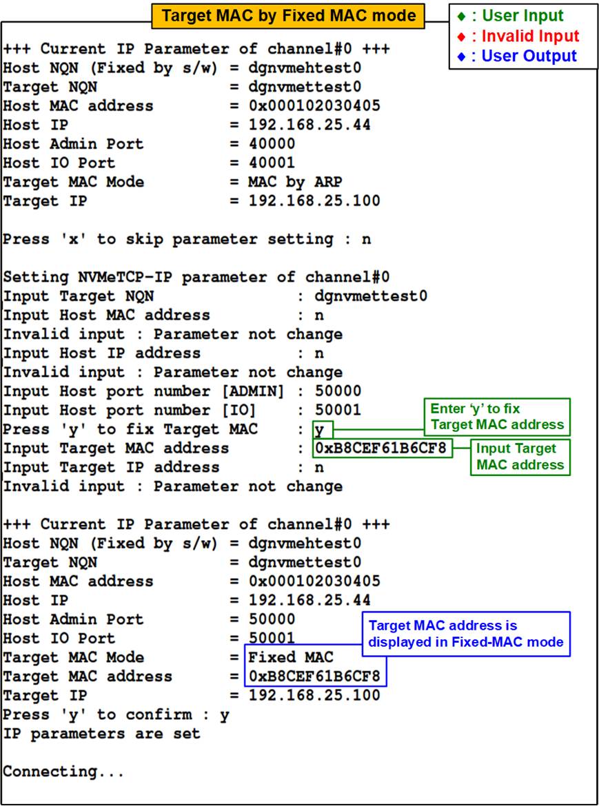
Figure 4‑2 Set Network Parameter result (Fixed MAC mode)
4.2 Write/Read Command
Select ‘1’ to either write or read the data with the Target. For Write command, the host will send a Write command along with write pattern across Ethernet to write to the SSD of the Target system. For Read command, the Host will send a Read command across Ethernet to the Target, and then wait for the received data which is read out from the SSD of the Target system.
Once this menu is selected, three values can be input for each Host channel, i.e., ‘0’-No operation, ‘1’-Write command, and ‘2’-Read command. Details for executing Write and Read command are provided below.
4.2.1 Write command
User inputs three parameters as follows.
1) Start Address: Input start address to write the SSD as 512-byte unit. The input is decimal unit when user enters only digit number. User can add “0x” to be prefix for hexadecimal unit. This input must be aligned to 16 because data length per Write command is fixed to 8192 bytes (16 x 512-byte).
2) Transfer Length: Input total transfer size as 512-byte unit. The input is decimal unit when user enters only digit number. User can add “0x” to be prefix for hexadecimal unit. This input must be aligned to 16 because data length per Write command is fixed to 8192 bytes.
3) Test pattern: Select test data pattern for writing to the SSD, which can be selected from four options, i.e., 32-bit incremental, 32-bit decremental, all 0, and all 1.
Note: Some SSDs shows the best performance when using all 0 pattern.
Once all the inputs have been validated, the system starts the Write operation. The console displays the amount of data transferred every second to indicate that the system is functioning correctly. After the operation is complete, the console displays the total size of the transfer, the time usage for the transfer, and test speed as the test results.
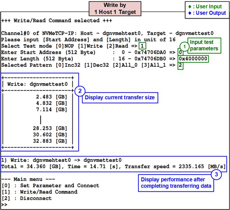
Figure 4‑3 Test result when executing Write command by 1 Host 1 Target
Figure 4‑3 displays the result of a Write command executed by a single Host. In this test environment, the Target is set up by a PC with a standard 25G NIC, but the maximum performance of 25G Ethernet cannot be achieved. The performance per 25G Ethernet connection is 2300 MB/s, which is 76.7% of the maximum line rate of 25G Ethernet, 3000 MB/s.
Typically, the operating system provides limited resources for handling each TCP session and utilizing multiple TCP sessions can result in better performance than a single session. An example of this testing is provided at the following website.
https://www.intel.com/content/www/us/en/support/articles/000005811/ethernet-products.html
When using an NVMeTCP25G-IP to be a Host, which employs a single TCP session for data transfer with the Target, performance can be increased if the Target system is set up using specific hardware such as Smart NIC or FPGA platform rather than a PC with standard OS and driver. According to the test report of TOE25G-IP, the maximum throughput of 25G Ethernet can be achieved when two TOE25G-IPs transfer the data to each other using a single session. However, when transferring data between TOE25G-IP and a PC using a single session, performance is reduced. More details are described in the following document.
https://dgway.com/products/IP/TOE25G-IP/dg_toe25gip_cpu_instruction.pdf
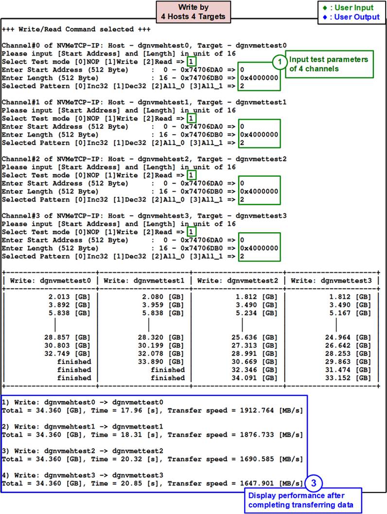
Figure 4‑4 Test result when executing Write command by 4 Hosts 4 Targets
Figure 4‑4 shows the test performance when four Hosts execute Write command. The four Target systems are set up by using two PCs, so two Target systems share the same PC resources for both PCIe bus and main memory. As a result, the performance per Host channel ranges 1600 to 1900 MB/s which is less than the result of a single Host displayed in Figure 4‑3.
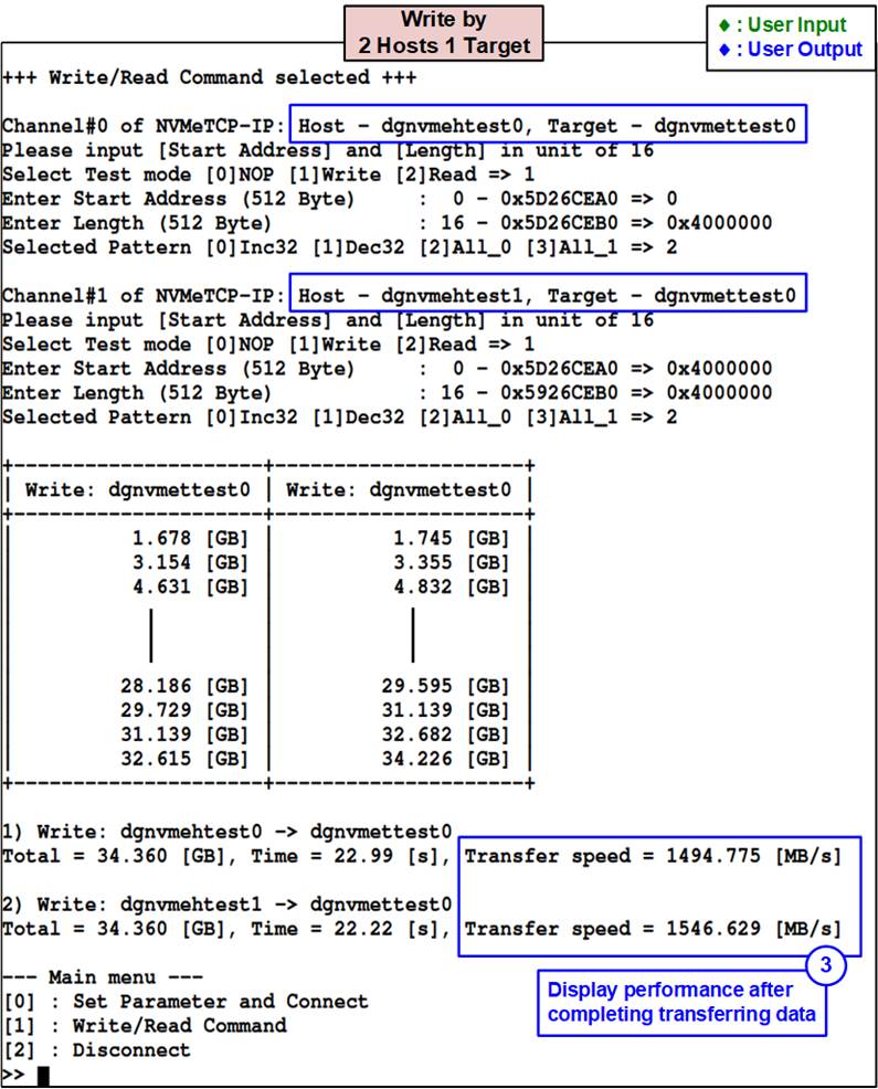
Figure 4‑5 Test result when executing Write command by 2 Hosts 1 Target
To increase the performance of a single Target system using PC with standard OS that limits the resource for each TCP session, two Hosts can be connected to the same Target through Ethernet switch. The result of a single Target system can increase from 2300 MB/s (Figure 4‑3) to 3040 MB/s (1494 + 1546 as shown in Figure 4‑5) which achieves the maximum line rate of 25G Ethernet connection.
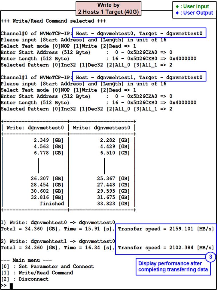
Figure 4‑6 Test result when executing Write command by 2 Hosts 1 Target @ 40G Ethernet
Since the Host and the Target can connect through Ethernet switch, the Ethernet connection of the Host and the Target can be set by different Ethernet speed. Figure 4‑6 shows the result when two Hosts by NVMeTCP25G-IP write the data to a single Target which uses 40G Ethernet connection. The performance per Host channel increases to 2100 MB/s, comparing with 1500 MB/s shown in Figure 4‑5.
Test data stored in the SSD is split into 8192-byte block. Each 8192-byte data has unique 64-bit header consisting of 48-bit address (in 512-byte unit) and 16-bit zero value. The remaining data is the test pattern which is selected by user. Figure 4‑7 shows the example when using 32-bit incremental pattern.
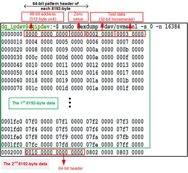
Figure 4‑7 Example Test data of the 1st and 2nd 8192-byte by using incremental pattern
Figure 4‑8 show the message when user executes Write or Read command but inputs the invalid value. The console displays “Invalid input” and then the operation is cancelled
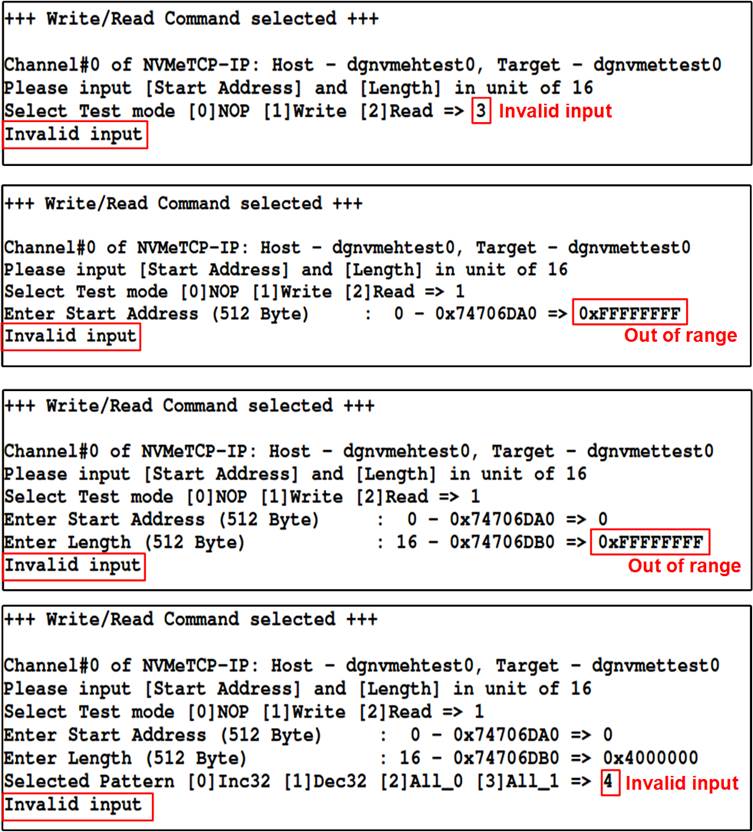
Figure 4‑8 Error message when the input is unaligned, out-of-range, or invalid
4.2.2 Read command
To read the target SSD, user inputs three parameters as follows.
1) Start Address: Input start address to read the SSD as 512-byte unit. The input is decimal unit when user enters only digit number. User can add “0x” to be prefix for hexadecimal unit. This input must be aligned to 16 because data length per Read command is fixed to 8192 bytes.
2) Transfer Length: Input total transfer size as 512-byte unit. The input is decimal unit when user enters only digit number. User can add “0x” to be prefix for hexadecimal unit. This input must be aligned to 16 because data length per Read command is fixed to 8192 bytes.
3) Test pattern: Select test data pattern to verify the received data from the SSD. Test pattern must be matched with the pattern using in Write Command menu. There are four options, i.e., 32-bit incremental, 32-bit decremental, all-0, and all-1.
Similar to Write command menu, test system reads data from the SSD when all inputs are valid. During reading data, the console displays the amount of transferred data every second. After the operation is complete, the console displays the total size of the transfer, the time usage for the transfer, and test speed as the test results.
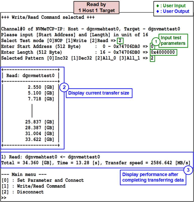
Figure 4‑9 Test result when executing Read command by 1 Host 1 Target
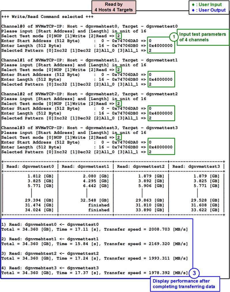
Figure 4‑10 Test result when executing Read command by 4 Hosts 4 Targets
Figure 4‑9 and Figure 4‑10 show the test result when executing Read command by one and four Hosts, respectively. When compared to the Write command, the performance of Read command is better, but it is still limited by the available Target resources. When using a single Host, it achieves 2580 MB/s or 86% of the maximum line rate of 25G Ethernet (3000 MB/s). However, the performance per channel when using four-channel test environment is reduced to 2000 MB/s, which is less than that of a single channel. The four-channel is set up by two PCs and two Targets are configured to share each PC resource.
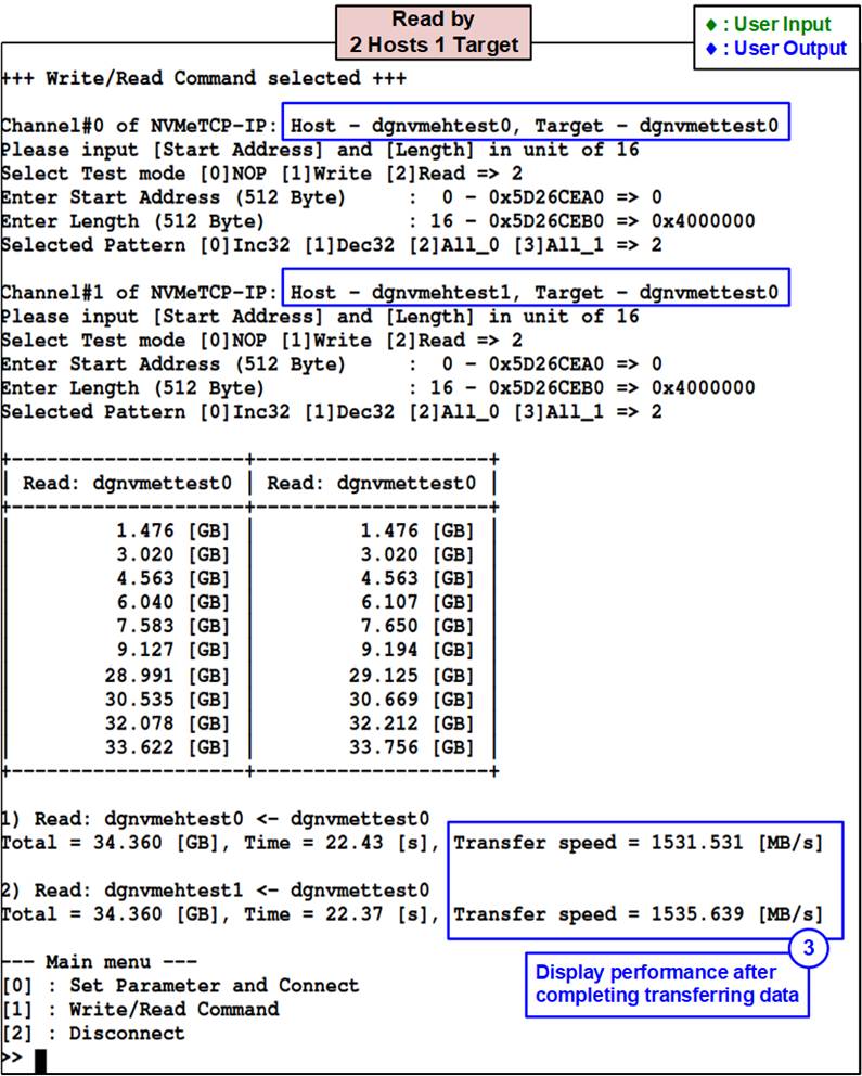
Figure 4‑11 Test result when executing Read command by 2 Hosts 1 Target
The performance when two Hosts transfer the data to the same Target via an Ethernet switch reaches the maximum line rate of 25G Ethernet. In this scenario, the total read performance of a single Target is 3066 MB/s, as displayed in Figure 4‑11, where 1531 MB/s and 1535 MB/s are achieved by each Host.
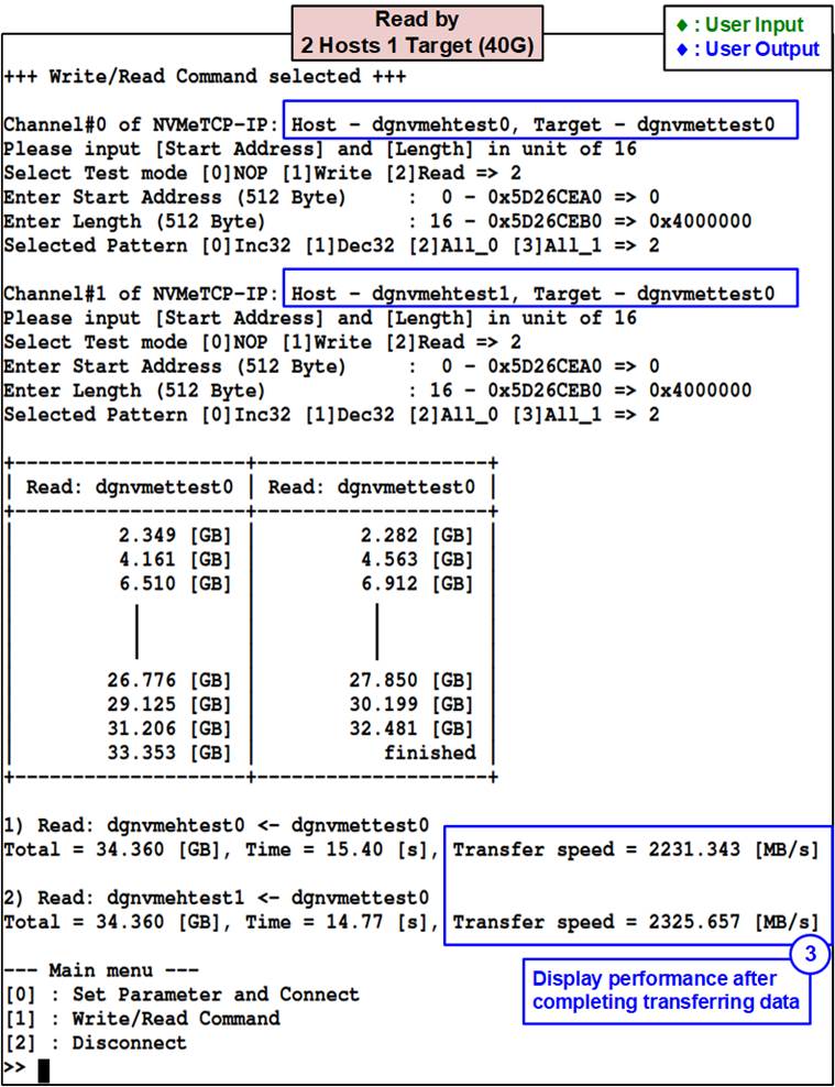
Figure 4‑12 Test result when executing Read command by 2 Hosts 1 Target @ 40G Ethernet
If a single Target’s Ethernet connection is upgraded from 25G to 40G speed, the total read performance with two Hosts is boosted to 4556 MB/s, with each Host performing 2231 MB/s and 2325 MB/s as illustrated. Increasing the number of Hosts will allow the maximum line rate of 40G Ethernet to be attained.
Figure 4‑13 shows the error message when data verification fails while executing Read command. The message “Verify fail” is displayed along with information on the first failure data, including the error byte address, the expected value, and the read value.
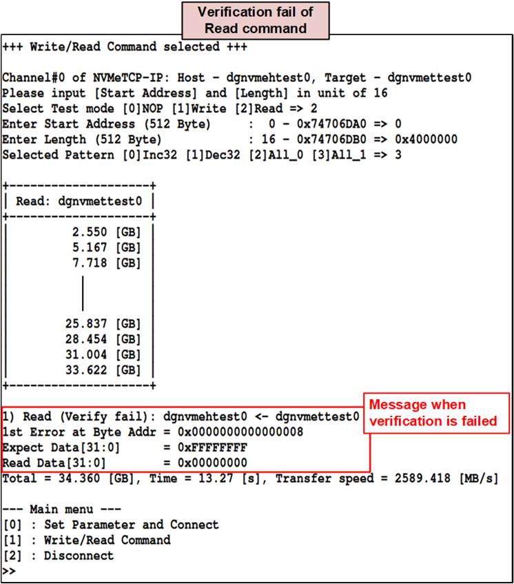
Figure 4‑13 Test result when data verification is failed
4.2.3 Mixed Write/Read command
The operation of each Host can be configured independently, so the Write command and the Read command can be executed simultaneously using different Host channels. Like the Write and Read commands, three parameters are required, as follows.
1) Start Address: Input start address to write/read the SSD as 512-byte unit. The input is decimal unit when user enters only digit number. User can add “0x” to be prefix for hexadecimal unit. This input must be aligned to 16 because data length per Write/Read command is fixed to 8192 bytes.
2) Transfer Length: Input total transfer size as 512-byte unit. The input is decimal unit when user enters only digit number. User can add “0x” to be prefix for hexadecimal unit. This input must be aligned to 16 because data length per Write/Read command is fixed to 8192 bytes.
3) Test pattern: Select test data pattern for writing/verifying data to/from the SSD. There are four options, i.e., 32-bit incremental, 32-bit decremental, all-0, and all-1.
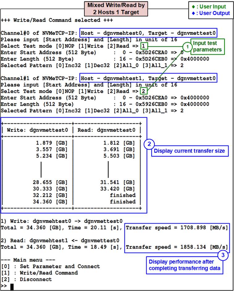
Figure 4‑14 Test result when executing mixed Write/Read command by 2 Hosts 1 Target
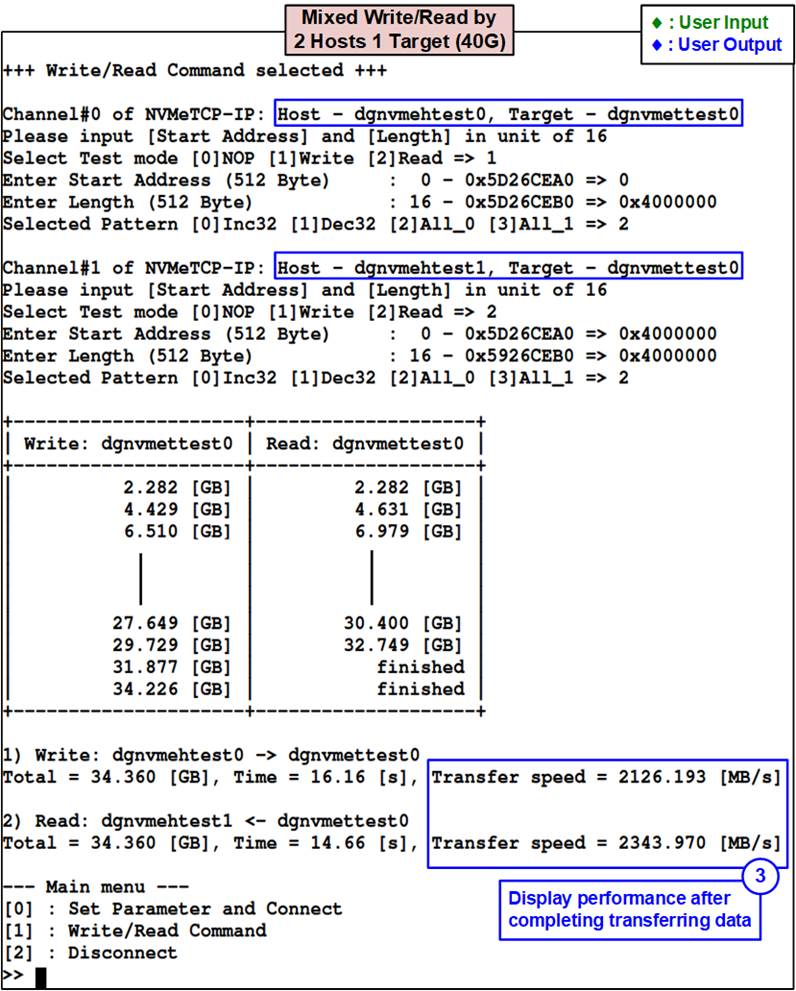
Figure 4‑15 Test result when executing mixed Write/Read command
by 2 Hosts 1 Target @ 40G Ethernet
Figure 4‑14 shows the test results when executing Write command by the first Host and Read command by the second Host, which transfers to the same Target via 25G Ethernet connection. Since the Ethernet connection supports full-duplex transmission, the overall performance of the two Hosts surpasses the 25G Ethernet line rate. Nevertheless, since both Tx and Rx transmission are required for data transfer in both directions for TCP/IP protocol, the performance per Host when executing a mixed Write/Read command is less than that of a single command. The performance result is approximately 1700 – 1800 MB/s per Host for mixed use. If the Ethernet connection is upgraded to 40G, as shown in Figure 4‑15, the performance per Host is increased to 2100 – 2300 MB/s.
4.3 Disconnect Command
Select ‘3’ to disconnect the Target from the selected Host. Once this menu is executed, the status of all connections is displayed. Next, the user sets the host channel to terminate the connection and then a confirmation message will be displayed on the console. User enters ‘y’ to proceed with the operation or enters other key to cancel the operation.
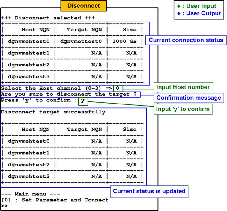
Figure 4‑16 Console result when running Disconnect command
After disconnecting from the Target successfully, the console will display a message confirming that the disconnection was successful along with the updated connection status. At this point, the user can proceed to change the IP parameters and establish a new connection between the Host and a different Target by selecting the menu [0] (Set Parameter and Connect command).
5 Revision History
|
Revision |
Date |
Description |
|
1.0 |
22-Feb-23 |
Initial version release |