NVMeTCP-IP Cloud Accelerator Demo Instruction
2 NVMe/TCP Target Setup on Linux PC
2.1 Default Kernel NVMe/TCP Target Setup
2.1.3 Remove NVMe/TCP Target configuration
2.2 SPDK NVMe/TCP Target Setup
3.1 Host Software Installation
3.3 Host System Initialization
3.3.2 Prepare the Configuration File
4 Write/Read Transfer Test on Unformatted SSDs
5 Write/Read Transfer Test with File System
5.1 Create Partition and File System
1 System overview
This document provides step-by-step instructions for configuring the Accelerator card and setting up the test environment to demonstrate host applications running on a virtual machine (VM) accessing remote storage via a 100G Ethernet connection. This demo system is a joint development by Design Gateway and DYNANIC.
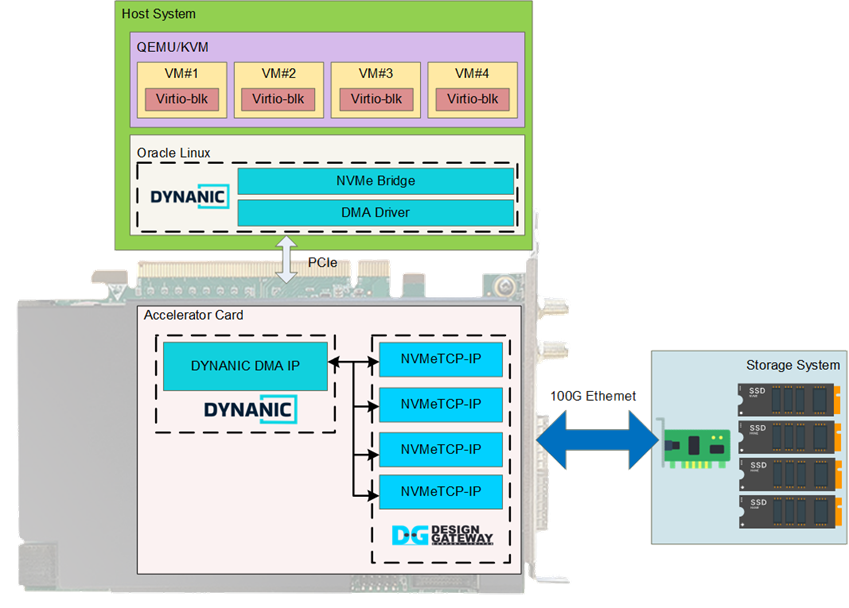
Figure 1 NVMeTCP-IP Cloud Accelerator Overview
The system utilizes the NVMe/TCP protocol for remote storage access, offering flexibility and scalability. To offload the CPU resources in the Host system from handling both TCP/IP and NVMe-oF protocols, the NVMeTCP IP core from Design Gateway is employed. This enables an access to the NVMe SSD without requiring additional CPU or memory resources. Each NVMeTCP-IP supports a single NVMe SSD access, and four NVMeTCP-IPs are integrated to demonstrate simultaneous access to four NVMe SSDs.
The Accelerator card connects to the Host system via a PCIe interface. DYNANIC provides a complete PCIe solution, including a DMA IP core and DMA Driver, to maximize throughput and achieve peak PCIe bandwidth on each FPGA card. Additionally, DYNANIC has developed an NVMe Bridge application to enable all VMs to access the NVMe SSDs in the remote system via a 100G Ethernet connection.
Further details of the hardware and software implementation are provided in this section. The following sections contain instructions for setting up and running the demo system.
1.1 Hardware
The Accelerator card integrates two IP cores: NVMeTCP-IP from Design Gateway and DYNANIC DMA-IP from DYNANIC, as detailed below.
NVMeTCP IP Core
Design Gateway provides the NVMeTCP IP core, a host controller that enables access to an NVMe SSD in the target system via Ethernet, utilizing the NVMe over TCP protocol. Once a connection is established, users can issue multiple Write and Read commands until the command queue reaches capacity. Each command transfers a fixed 4 KB data block.
The command interface operates via a memory-mapped interface, facilitating the transmission of commands along with their corresponding 4 KB data blocks. Detailed specifications and further information about the IP core can be found on the Design Gateway website: https://dgway.com/solutions.html#Cloud
DYNANIC DMA IP
The DYNANIC DMA IP is integrated into the Network Development Kit (NDK), a high-performance framework for FPGA-based networking applications developed by CESNET. It provides a set of optimized FPGA IP cores and software tools, achieving data transfer speeds over 400 Gbps between the host computer's memory and the Accelerator card. This high-speed communication is enabled by an advanced DMA module IP and an efficient software layer.
While the NDK framework is open-source, the DYNANIC DMA IP itself is proprietary and is not included in the open-source release. Further detailed about the DMA IP can be found on the DYNANIC website: https://dyna-nic.com/.
1.2 Software
DYNANIC implements a software suite that enables multiple virtual machine (VM) users to access NVMe SSDs via the NVMe/TCP protocol. This suite includes the DMA driver, the NVMe-Bridge application, and the Virtual machine software stack. The details of each component are described below.
DMA Driver
The DMA Driver works alongside the DYNANIC DMA IP to facilitate high-speed PCIe data transfers between the Host system and the Accelerator card. It provides control over hardware components while efficiently managing data movement between the host and the Accelerator card.
NVMe-Bridge Application
The NVMe-Bridge Application acts as an interface between the VMs and the NVMeTCP-IP, enabling NVMe/TCP communication with remote NVMe storage. It manages and distributes storage access requests from VMs across multiple NVMe/TCP connections to optimize performance.
The NVMe-Bridge application supports four different algorithms for handling write and read operations with the NVMeTCP IP core. Each algorithm optimizes performance differently by varying the way storage requests are distributed and processed. All algorithms are listed in Table 1.
Table 1 NVMe Bridge Algorithms
|
Algorithm |
Description |
|
0 – Simple Sequential Mode |
A basic sequential algorithm that processes requests one at a time. This mode is primarily for debugging and does not optimize performance. |
|
1 – Interleaved Block Mode |
Handles multiple storage blocks at once, allowing write and read operations to be interleaved efficiently. Improves throughput compared to sequential processing. |
|
2 – Interleaved Multi-Core Mode |
Distributes storage blocks across multiple NVMeTCP-IPs, maximizing parallelism. This increases performance by utilizing multiple NVMeTCP-IPs concurrently. |
|
3 – Interleaved Multi-Core with Separate Read/Write |
Further optimizes performance by distributing write and read operations separately across multiple NVMeTCP-IPs. Useful for workloads with mixed write/read operations. |
|
4 – Thread-Based Multi-Core Mode |
Each NVMeTCP-IP operates as a separate virtual block device within the VM, with independent threads handling I/O. Requires each core to be connected to a separate NVMe/TCP target to avoid data corruption. |
Note: Running NVMe-Bridge with Algorithm 4 will result in four disks
appearing in the virtual machine, while Algorithms 0-3 will present only a
single disk. This difference affects both the configuration process and the
console output, which will be discussed separately for Algorithm 0-3 and
Algorithm 4 throughout the instructions.
Virtual Machine Software Stack
The virtual machine software stack integrates three essential components to facilitate efficient virtualization and storage management: QEMU/KVM, virt-manager, and virtio-blk.
QEMU (Quick Emulator) functions as a hardware emulator and virtual machine monitor, providing device emulation for components such as network interfaces and storage devices. When combined with the Kernel-based Virtual Machine (KVM), it enables efficient hardware-assisted virtualization by handling CPU and memory virtualization tasks.
To simplify the management of these virtual machines, virt-manager (Virtual Machine Manager) offers a graphical user interface, allowing users to create, configure, and monitor VMs without delving into complex command-line operations.
Within this framework, virtio-blk serves as a paravirtualization block device driver, optimizing disk I/O operations between the host and guest systems by presenting virtual storage devices to the guest operating systems.
2 NVMe/TCP Target Setup on Linux PC
This section explains how to configure an NVMe SSD on the target system, so it can be accessed by the host via Ethernet interface using the NVMe/TCP protocol. This document demonstrates two configuration options: default Kernel NVMe/TCP Target and SPDK (Storage Performance Development Kit) NVMe/TCP Target. Before setting up the NVMe/TCP Target, the Ethernet interface must be configured by following the steps below.
Ethtool Installation
Ethtool is a utility used to optimize network card performance. To install it, open a terminal and run:
>> sudo apt install ethtool
This installation only needs to be performed once on the Linux PC.
Ethernet Interface Configuration
To achieve optimal performance for the 100G Ethernet network card, follow these steps:
1) Open a terminal and use the following command to list the logical name of the 100G Ethernet port on the Linux system:
>> sudo lshw -C network
The command output (as shown in Figure 2) identifies the 100G Ethernet interface connected to the NVMe/TCP host, labeled as “enp1s0f0”.
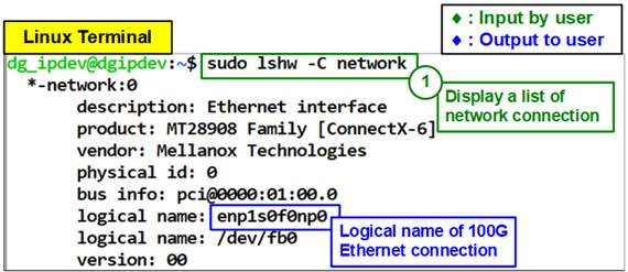
Figure 2 Display Logical Name of 100G Ethernet Port
The command output (as shown in Figure 2) identifies the 100G Ethernet interface connected to the NVMe/TCP host, labeled as “enp1s0f0”.
To verify the Ethernet speed (100G Ethernet), run the following command:
>> ethtool enp1s0f0 2>/dev/null | grep -i Speed
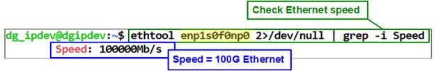
Figure 3 Verify Ethernet Speed
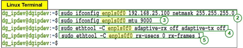
Figure 4 IP Address and Ethernet Interface Setting
2) Set the IP address and subnet mask for the Ethernet interface using: “sudo ifconfig <interface> <ipaddr_value> netmask <netmask_value>”. For this setup:
· Interface: enp1s0f0
· IP address: 192.168.25.100
· Subnet mask: 255.255.255.0
Run the following command:
>> sudo ifconfig enp1s0f0 192.168.25.100 netmask 255.255.255.0
3) Enable jumbo frames by setting the Maximum Transfer Unit (MTU) to 9000 to allow jumbo frame for improved performance: “sudo ifconfig <interface > mtu <mtu_value>”. For this setup:
>> sudo ifconfig enp1s0f0 mtu 9000
4) To stabilize performance, disable the adaptive Rx-Tx latency improvement algorithm with: “sudo ethtool -C <interface> adaptive-rx off adaptive-tx off”. For this setup:
>> sudo ethtool -C enp1s0f0 adaptive-rx off adaptive-tx off
5) Set the highest rate of Rx interrupts to ensure the PC processes each received packet immediately: “sudo ethtool -C <interface> rx-usecs 0 rx-frames 1”. For this setup:
>> sudo ethtool -C enp1s0f0 rx-usecs 0 rx-frames 1
Once the Ethernet interface is successfully configured, the user can choose to set up the NVMe/TCP Target using either the default Kernel NVMe/TCP Target or the SPDK NVMe/TCP Target. Further details on each configuration are provided below.
2.1 Default Kernel NVMe/TCP Target Setup
This section outlines the steps to configure the Linux Kernel NVMe/TCP Target, including installing nvme-cli, setting up the target, and performing cleanup after the process is complete.
2.1.1 Install nvme-cli
The nvme-cli is used to manage NVMe SSDs on a Linux OS. To install it, run the following command in the terminal:
>> sudo apt install nvme-cli
Note: The nvme-cli package only needs to be installed once per Linux PC.
2.1.2 Set NVMe/TCP Target
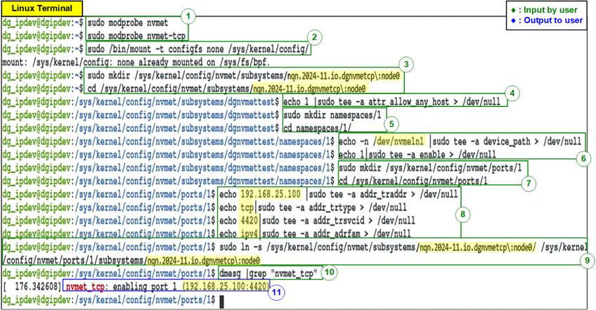
Figure 5 Linux Kernel NVMe/TCP Target Setting
1) Run the following command to load the NVMe/TCP target modules:
>> sudo modprobe nvmet
>> sudo modprobe nvmet-tcp
2) Mount the kernel user configuration filesystem to manage NVMe/TCP target settings.
>> sudo /bin/mount -t configfs none /sys/kernel/config/
3) Create an NVMe target subsystem and define the NVMe Qualified Name (NQN). In this demo, the NQN is configured as “nqn.2024-11.io.dgnvmetcp\:node0”. Use the following commands to create the subsystem (one per SSD):
>> sudo mkdir /sys/kernel/config/nvmet/subsystems/nqn.2024-11.io.dgnvmetcp\:node0
>> cd /sys/kernel/config/nvmet/subsystems/nqn.2024-11.io.dgnvmetcp\:node0
4) Set the attribute to allow any host to connect using the following command.
Note: This setting is suitable for testing but should be restricted in production environments.
>> echo 1 |sudo tee -a attr_allow_any_host > /dev/null
5) Create a namespace for the subsystem and navigate to its directory:
>> sudo mkdir namespaces/1
>> cd namespaces/1/
6) Assign an NVMe SSD to the namespace and enable it:
>> echo -n /dev/nvme1n1 |sudo tee -a device_path > /dev/null
>> echo 1|sudo tee -a enable > /dev/null
7) Create an NVMe target port to export the created subsystem and navigate to its directory:
>> sudo mkdir /sys/kernel/config/nvmet/ports/1
>> cd /sys/kernel/config/nvmet/ports/1
8) Configure Ethernet parameters for the NVMe target port. Set the required network parameters:
· IP address = 192.168.25.100
· Transport type = tcp
· Port number = 4420
· Address family = ipv4
Note: Ensure the IP address corresponds to your network setup.
>> echo 192.168.25.100 |sudo tee -a addr_traddr > /dev/null
>> echo tcp | sudo tee -a addr_trtype > /dev/null
>> echo 4420 | sudo tee -a addr_trsvcid > /dev/null
>> echo ipv4 | sudo tee -a addr_adrfam > /dev/null
9) Create a symbolic link between the target port and the subsystem:
>> sudo ln -s /sys/kernel/config/nvmet/subsystems/nqn.2024-11.io.dgnvmetcp\:node0/ /sys/kernel/config/nvmet/ports/1/subsystems/nqn.2024-11.io.dgnvmetcp\:node0
Note: The Target NQN (nqn.2024-11.io.dgnvmetcp:node0) matches the value configured in step 3).
10) Check system messages to confirm the NVMe/TCP target is set up correctly:
>> dmesg |grep "nvmet_tcp"
11) If the setup is successful, the system messages will display the target IP address and port number, as shown in Figure 6.
![]()
Figure 6 NVMe/TCP Target Setup Success Message
2.1.3 Remove NVMe/TCP Target configuration
This section provides step-by-step instructions for removing the NVMe/TCP target configuration on a Linux PC after completing the tests, as shown in Figure 7.
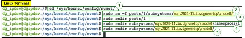
Figure 7 Remove NVMe/TCP Target
1) Run the following command to navigate to the directory where NVMe/TCP configurations are stored:
>> cd /sys/kernel/config/nvmet/
2) Delete the directory corresponding to the target port to remove its connections:
>> sudo rm -f ports/1/subsystems/nqn.2024-11.io.dgnvmetcp\:node0
>> sudo rmdir ports/1
3) Run the following commands to remove the subsystems associated with the NVMe SSD:
>> sudo rmdir subsystems/nqn.2024-11.io.dgnvmetcp\:node0/namespaces/1
>> sudo rmdir subsystems/nqn.2024-11.io.dgnvmetcp\:node0/
Once the target subsystem is successfully removed, the NVMe SSD should be accessible by the standard NVMe device driver on the PC. To verify the written data, you can use tools such as “hexdump” or other disk inspection utilities.
By following these steps, you can ensure the NVMe/TCP target configuration is properly removed, and the NVMe SSD is restored to its standard operational state for regular PC usage.
2.2 SPDK NVMe/TCP Target Setup
To configure the NVMe/TCP target using SPDK, first set up the SPDK NVMe/TCP target by initializing the SPDK environment and configuring the NVMe SSD as a target device. After completing the test, unbind the NVMe SSD from SPDK to return it to its original state for further use or other configurations.
2.2.1 Install SPDK
To install SPDK follow the “Getting Started” topic from SPDK website: https://spdk.io/doc/getting_started.html
2.2.2 Set NVMe/TCP Target
To configure the NVMe/TCP target, use the scripts and applications provided by SPDK. Follow the steps below to complete the setup. The Linux terminal during the SPDK setup process is illustrated in Figure 8.
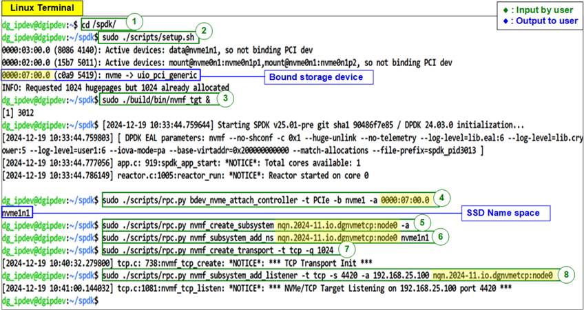
Figure 8 SPDK NVMe/TCP Target Setting
1) Navigate to the SPDK directory.
>> cd <SPDK_directory>/SPDK
2) Setup the SPDK. This process automatically binds SPDK to the storage device. The script will detect and bind to the inactive PCI device. Additionally, the allocation of huge pages is done in this step.
>> sudo ./scripts/setup.sh
Note: The bound storage device is displayed on the terminal. This value is required as input in Step 4).
3) Run the “nvmf_tgt” application in background. Use the ‘&’ symbol to allow the application to run in background:
>> sudo ./build/bin/nvmf_tgt &
4) Attach the controller to the NVMe device. Use the ‘-a’ flag to specify the PCIe address of the corresponding NVMe device. After attaching, the application returns the namespace.
>> sudo ./scripts/rpc.py bdev_nvme_attach_controller -t PCIe -b nvme1 -a 0000:07:00.0
Namespace output example:
>> nvme1n1
5) Create an NVMe subsystem. This step creates an NQN (NVMe Qualified Name). The NQN must follow the format: “nqn.<date>.<organization_identifier>:<unique_identifier>”.
Use the ‘-a’ flag to allow any host to access it.
>> sudo ./scripts/rpc.py nvmf_create_subsystem nqn.2024-11.io.dgnvmetcp:node0 -a
6) Add a namespace to the subsystem:
>> sudo ./scripts/rpc.py nvmf_subsystem_add_ns nqn.2024-11.io.dgnvmetcp:node0 nvme1n1
7) Create the NVMe/TCP transport. Adjust the queue depth using the ‘-q’ flag to make it compatible with DG NVMeTCP-IP. The queue depth must be at least 512.
>> sudo ./scripts/rpc.py nvmf_create_transport -t tcp -q 1024
8) Add the listener
>> sudo ./scripts/rpc.py nvmf_subsystem_add_listener -t tcp -s 4420 -a 192.168.25.100
nqn.2024-11.io.dgnvmetcp:node0
2.2.3 Clean Up SPDK target
After completing the testing process, the SPDK must be cleaned up to stop the “nvmf_tgt” application and return the SSD to the Linux Kernel.
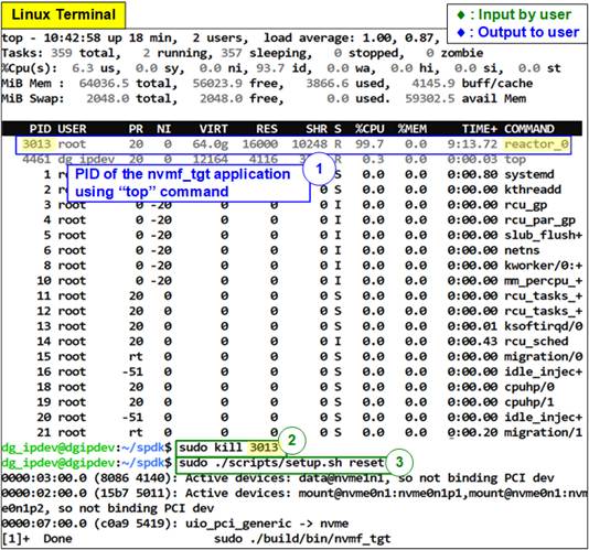
Figure 9 Clean Up SPDK Target
1) Run the following command to display running processes and identify the PID of the “nvmf_tgt application (reactor_0):
>> top
2) Use the kill command followed by the PID from Step 1) to stop the “nvmf_tgt: application. If PID=3013, run:
>> sudo kill 3013
3) Use the following command to automatically unbind the SSD from SPDK and restore it to the Linux kernel:
>> sudo
./scripts/setup.sh reset
3 Host System Setup
This section covers the setup of the Host system and virtual machine, including installing essential tools, applying required configurations to the Host system, downloading and installing the virtual machine, setting up dependencies, and configuring the virtual machine.
To setup the Accelerator card to the Host system for this demo, please follow the instructions available in the FPGA setup document for this demo on our website.
3.1 Host Software Installation
1) Run the following commands to enable the necessary repositories on Oracle Linux 8:
>> sudo dnf install oracle-epel-release-el8.x86_64
>> sudo dnf config-manager --set-enabled ol8_developer_EPEL
>> sudo dnf config-manager --set-enabled ol8_codeready_builder
>> sudo dnf config-manager --set-enabled ol8_baseos_latest
>> sudo dnf config-manager --set-enabled ol8_appstream
>> sudo dnf config-manager --set-enabled ol8_developer_EPEL_modular
2) Run the appropriate command based on your kernel version to install kernel headers and setup DKMS build:
For Kernel 4.18,
>> sudo dnf install kernel-headers
For Kernel 5.15,
>> sudo dnf install kernel-uek-devel
>> scl enable gcc-toolset-11 /bin/bash
3) Run the following command to install nvme-bridge from the provided file:
>> sudo dnf localinstall -y nfb-framework-<software version>.el8.x86_64.rpm
Note: If the installation on Kernel 5.15 fails using the command above, run the following two commands instead.
>> sudo sed -i 's/obj-$(CONFIG_NFB_XVC)/#obj-$(CONFIG_NFB_XVC)/g'
/var/lib/dkms/nfb-dkms/6.21.1-1/source/kernel/drivers/Makefile
>> sudo dkms install nfb-dkms/6.21.1-1
Then, proceed with the following installation commands:
>> sudo dnf localinstall -y dpdk-nfb-<software version>.el8.x86_64.rpm \
dpdk-nfb-tools-<software version>.el8.x86_64.rpm \
dpdk-nfb-devel-<software version>.el8.x86_64.rpm
>> sudo dnf localinstall -y blc-<software version>.el8.x86_64.rpm
>> sudo dnf localinstall -y nvme-bridge-<software version>.el8.x86_64.rpm
Note: For example, if the software version is 22.11.104-4, the command parameter would be:
dpdk-nfb-devel-22.11.104-4.el8.x86_64.
3.2 Virtual Machine Setup
1) Run the following commands to install the required virtualization packages:
>> sudo dnf module install -y virt
>> sudo dnf install -y virt-install virt-viewer virt-manager
2) Update QEMU settings by replacing the configuration file located at /etc/lib/virt/qemu.conf with the provided file of the demo set “qemu.conf”.
3) Download the Debian12 image (debian-12-nocloud-amd64-20240211-1654.qcow2) from the following link:
4) Open virt-manager and follow the steps shown in Figure 10 to create a new virtual machine.
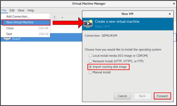
Figure 10 Create Virtual Machine
5) Choose the virtual machine image (qcow2 file) obtained in Step 2 as the installation source. The selection process is illustrated in Figure 11.
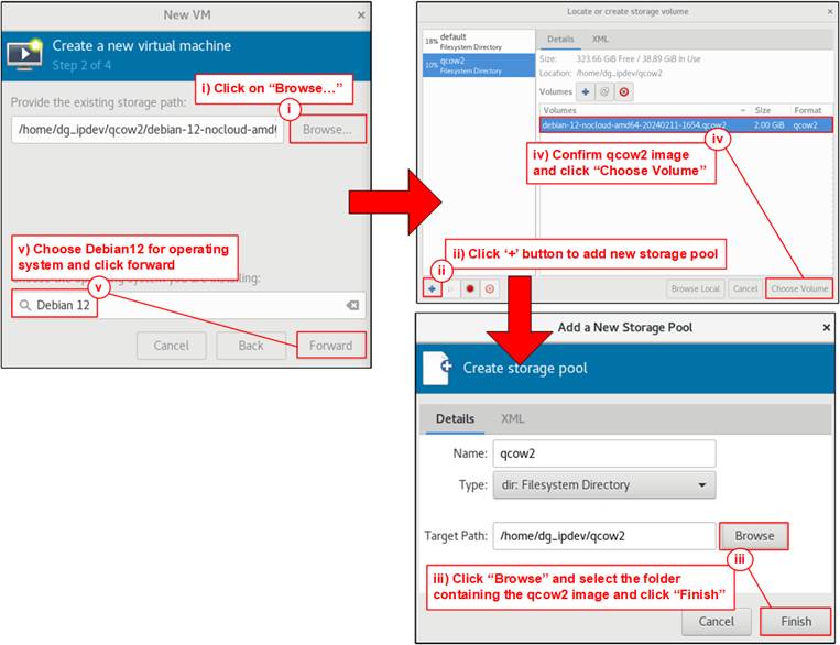
Figure 11 Choose Virtual Machine Image
6) Set the following recommended values: CPU Cores = 8 and Memory = 2048 MB (2 GB). This step is illustrated in Figure 12.
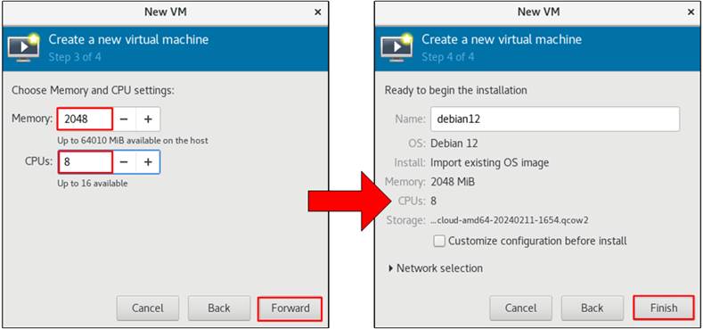
Figure 12 Configure Memory and CPU
Cores for Virtual Machine
7) Follow the steps in Figure 13 to open the created virtual machine.
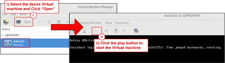
Figure 13 Open Virtual Machine
8) Install FIO (for write/read performance testing). The installation steps are shown in Figure 14.
i) Log in as the root user:
>> root
ii) Update the packet list:
>> apt-get update
>> apt-get -y install fio
iv) Power off the virtual machine:
>> poweroff
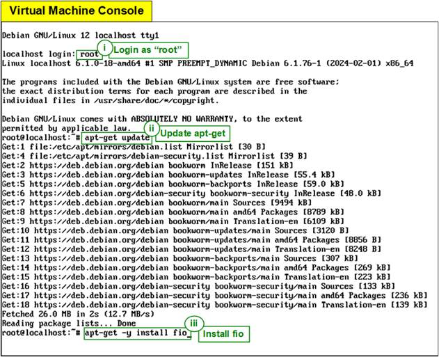
Figure 14 Tool Installation
9) Select “Enable XML editing” to allow virtual machine modification via XML file, as shown in Figure 15.
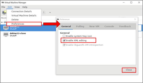
Figure 15 Enable XML Editing
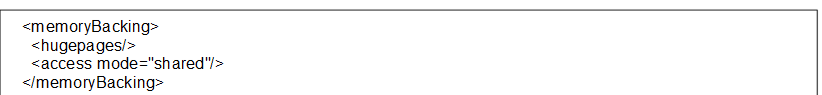
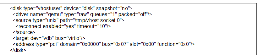
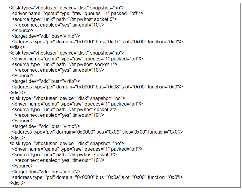
10) Modify the XML configuration file to add an additional storage device for the virtual machine. As shown in Figure 16, open the XML file and insert the configuration using the following steps.
i) Select the “Show virtual hardware details” icon.
ii) Navigate to the Overview menu.
iii) Open the XML tab and insert two configuration settings (“memoryBacking” and “disk”) into the XML file. The specific settings depend on the selected algorithm.
memoryBacking
(All Algorithms)
disk (Algorithm 0-3)
disk (Algorithm 4)
For more details on nvme-bridge algorithms, refer to Section 3.3.3 (Run nvme-bridge).
Note: After updating the configuration file, the virtual machine will not start until the “nvme-bridge” application is executed and connected to the target system. Ensure “nvme-bridge” is running and properly configured before attempting to start the virtual machine.
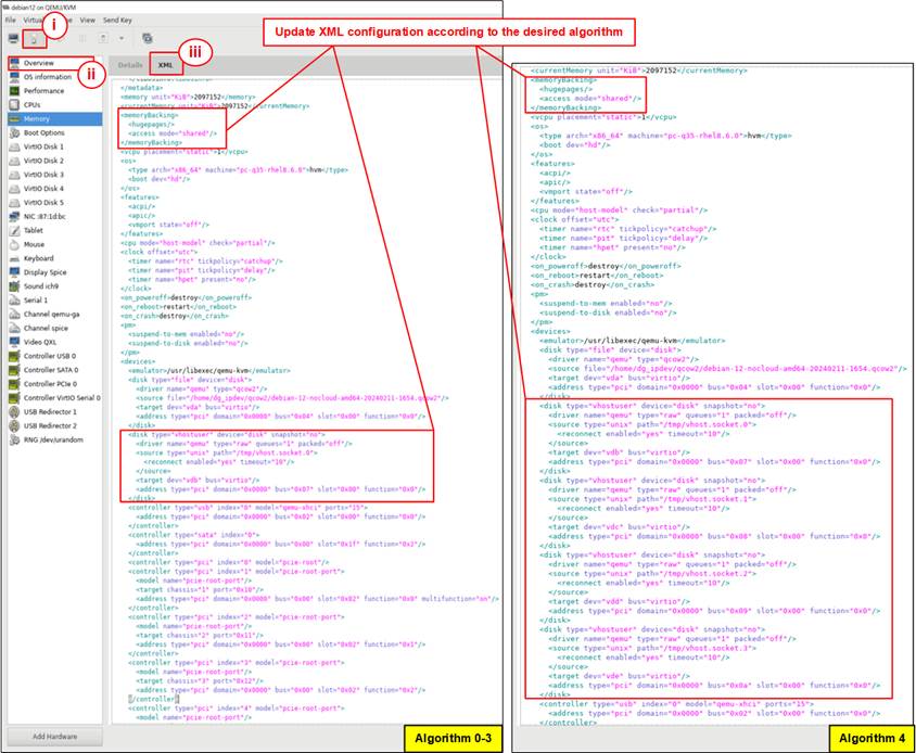
Figure 16 Update XML Configuration
3.3 Host System Initialization
The Host system is initialized to prepare the virtual machine for connection to the NVMe/TCP target system. This process involves configuring the host environment, which includes setting up the host before the connection, and preparing the configuration file to set the connection parameters. Finally, the "nvme-bridge" is run to establish the connection between the host virtual machine and the target SSD.
3.3.1 Set up Host Environment
Before running “nvme-bridge”, the Host system must be initialized as shown in Figure 17.
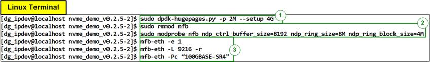
Figure 17 Setup Environment
1) Allocate huge pages for the environment:
>> sudo dpdk-hugepages.py -p 2M --setup 4G
2) Set up the NFB module parameters by running:
>> sudo rmmod nfb
>> sudo modprobe nfb ndp_ctrl_buffer_size=8192 ndp_ring_size=8M ndp_ring_block_size=4M
3) Enable Ethernet interface on the card and configure parameters:
>> nfb-eth -e 1
>> nfb-eth -L 9216
>> nfb-eth -Pc “100GBASE-SR4”
3.3.2 Prepare the Configuration File
The configuration file defines the connection parameters for each NVMeTCP-IP module in JSON format. Figure 18 provides an example configuration file for both a single NVMeTCP-IP and a four NVMeTCP-IP setup.
Note: When using Algorithm 4, all four NVMeTCP-IPs (index numbers 0 to 3) must be configured. For other Algorithms, one to four NVMeTCP-IPs can be selected in the “nvme_bridge” configuration file.
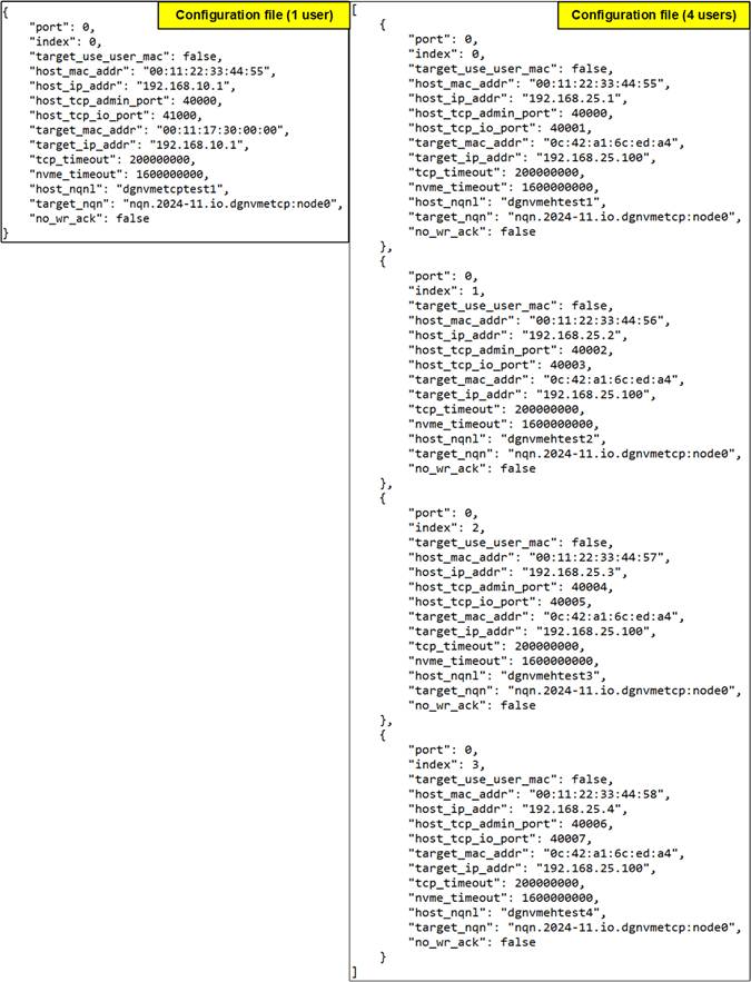
Figure 18 “nvme-bridge” Configuration File
The parameters listed below should be set according to your test environment:
· port: Ethernet port number on the Accelerator card. Set to 0.
· index: The index of the NVMeTCP IP core, ranging from 0 to 3.
· target_use_user_mac: Option to retrieve the NVMe/TCP target MAC address.
· “true”: The MAC address of the NVMe/TCP target is manually assigned using “target_mac_addr”. Use this when the Host system and the NVMe/TCP target system are on different networks that cannot use ARP packet transfer to retrieve the MAC address from the IP address.
· “false” The MAC address of the NVMe/TCP target is automatically retrieved via ARP packet transfer.
· host_mac_address: The local MAC address, provided as a 12-digit hexadecimal value with bytes separated by colons (“:”).
· host_ip_addr: The local IP address, formatted as four decimal numbers separated by dots (.), with each segment ranging from 0 to 255.
· host_tcp_admin_port: The local TCP port number used for Admin functions, with valid values ranging from 0 to 65,535.
· host_tcp_io_port: The local TCP port number used for I/O operations, with valid values ranging from 0 to 65,535.
· target_mac_addr: Required only when “target_use_user_mac” is set to “true”. This value represents the MAC address of the NVMe/TCP target, provided as a 12-digit hexadecimal value with bytes separated by colons (“:”).
· target_ip_addr: The IP address of the NVMe/TCP target, formatted as four decimal numbers separated by dots (.), with each segment ranging from 0 to 255.
· tcp_timeout: The timeout duration (in clock cycle units) to detect packet loss and start packet recovery. Typically set to 1 second. If the base clock frequency is 200 MHz, set this value to 200,000,000 for a 1-second timeout. Valid range is 1 to 4,294,967,295.
· nvme_timeout: The timeout duration (in clock cycle units) to wait for a response from the NVMe/TCP target before triggering an error assertion. Typically set to four times the “tcp_timeout” value. A value of 0 means there is no time limit for waiting for the response. Valid range is 0 to 4,294,967,295.
· “host_nqnl”: The NVMe Qualified Name (NQN) assigned to the Host, up to 16 characters.
· “target_nqn”: The NQN of the NVMe/TCP target. In this demo, it must be set to:
“ngn.2024-11.io.dgnvmetcp:node0”.
· “no_wr_ack”: Set to “false” to disable write acknowledgement to the software.
3.3.3 Run nvme-bridge
Run “nvme-bridge” to apply the parameters from the configuration file to the NVMeTCP-IP and establish the connection between the host and the target.
1) Confirm the Ethernet link status using the command below:
>> nfb-eth -i 0
The result should match Figure 19.
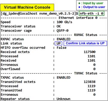
Figure 19 Check Ethernet Link Status
2) Run “nvme-bridge” using the following command:
>> sudo nvme-bridge -m 1024 -- -c config.multi.json -a 4 -p 4
Command parameters:
-m: Memory to allocate (in MB).
-c: Path to the nvme-bridge configuration file (JSON format).
-p: Number of active NVMeTCP IP cores (Valid values: 1 to 4).
-a: Algorithm selection for distributed write/read operations using NVMeTCP-IP (Valid values: 0 to 4).
A description for each algorithm is provided in Table 1.
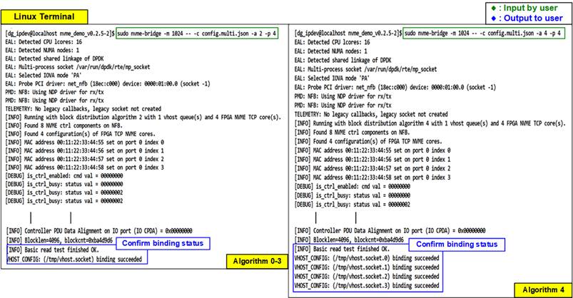
Figure 20
Run “nvme-bridge”
4 Write/Read Transfer Test on Unformatted SSDs
This section covers the performance testing of write/read operations on a non-partitioned SSD using FIO. First, start the virtual machine as shown in Figure 13. If the virtual machine fails to start or encounters an error, verify the binding status (Figure 20) and ensure the selected algorithm matches the XML configuration (Figure 16).
1) Log in to the virtual machine login as root.
2) Run the following command to check if the bound SSD is detected and verify its disk size:
>> lsblk
The output should match Figure 21, with variations only in the disk size.
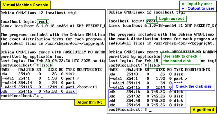
Figure 21 Check Disk Size
3) Prepare the FIO configuration file for testing. Create a FIO configuration file using the nano editor:
>> nano test.fio
Enter the parameter shown in Figure 22, and then save the file by pressing:
i) Ctrl + X
ii) Y
iii) Enter
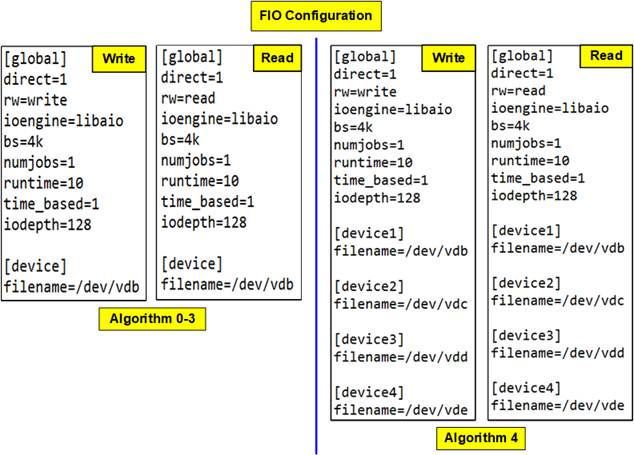
Figure 22 FIO Configuration File (No File System)
Note: The FIO command can be run directly without a configuration file. However, using a configuration file is recommended for reproducibility. An example of a direct command is shown below:
>> fio --direct=1 --rw=read --ioengine=libaio --bs=4k --numjobs=1 --runtime=10 --time_based=1 --iodept=128 --filename=/dev/vdb
4) Execute the FIO test using the configuration file:
>> fio test.fio
Once the test is complete, the virtual machine console will display the performance results, similar to Figure 23 for Algorithm 0-3 and Figure 24 for Algorithm 4.
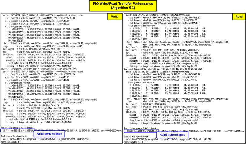
Figure 23 FIO Write/Read Transfer Performance (Algorithm 0-3)
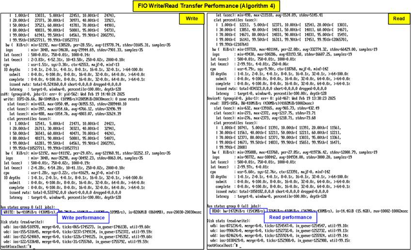
Figure 24 FIO Write/Read Transfer Performance (Algorithm 4)
5 Write/Read Transfer Test with File System
This section outlines the steps to mount the SSD and test its write/read performance using FIO on the mounted storage.
5.1 Create Partition and File System
Figure 25 shows the detailed steps to create the new partition and file system.
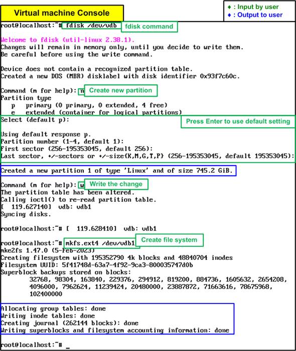
Figure 25 Create Partition and File System
1) Create a partition using the “fdisk” command with the relevant device:
>> fdisk /dev/vdb
2) Use the “n” command to create a new partition.
3) Press “Enter” for all parameters to accept the defaults.
4) Use the “w” command to write the changes to the disk.
5) Create a file system on the newly created partition using the “mkfs.ext4” command:
>> mkfs.ext4 /dev/vdb1
6) Wait until all the process is complete, and then reboot the virtual machine using GUI or following command:
>> reboot
5.2 FIO Test
1) Mount the file system on the newly created partition:
>> mkdir /mnt/vdb
>> mount /dev/vdb1 /mnt/vdb
2) Prepare the FIO configuration file for testing. Create a FIO configuration file using the nano editor:
>> nano test.fio
Enter the parameter shown in Figure 26, and then save the file by pressing:
i) Ctrl + X
ii) Y
iii) Enter
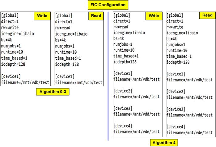
Figure 26 FIO Configuration File with File System
3) Execute the FIO test using the configuration file:
>> fio test.fio
Once the test is complete, the virtual machine console will display the performance results, similar to Figure 27 for Algorithm 0-3 and Figure 28 for Algorithm 4.
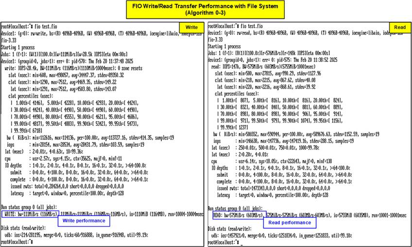
Figure 27 FIO Write/Read Transfer Performance with File System (Algorithm 0-3)
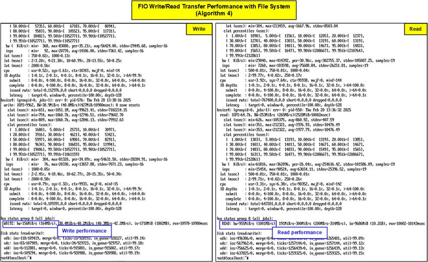
Figure 28 FIO Write/Read Transfer Performance
with File System (Algorithm 4)
6 Revision History
|
Revision |
Date (D-M-Y) |
Description |
|
1.00 |
19-Mar-25 |
Initial version release |