UDP10G-IP Core Data Sheet

Core Facts |
|
|
Provided with Core |
|
|
Documentation |
Design Guide |
|
Design File Formats |
Encrypted File |
|
Instantiation Templates |
VHDL |
|
Reference Designs & Application Notes |
Quartus Project, See Reference Design Manual |
|
Additional Items |
Demo on Arria10 GX/Arria10 SoC Development Board |
|
Support |
|
|
Support Provided by Design Gateway Co., Ltd. |
|
Design Gateway Co.,Ltd
E-mail: ip-sales@design-gateway.com
URL: design-gateway.com
Features
· Implementation of a UDP/IP stack
· Support for the IPv4 protocol
· Full-duplex data transfer using two port numbers for each direction
· Capability to handle multiple sessions using multiple UDP10G-IPs
· Support for Jumbo frame
· Packet transmission size aligned with a 64-bit data bus
· Total number of received data aligned to 64-bit data bus
· Adjustable transmit/receive buffer sizes for resource usage and performance optimization
· Simple data interface through a standard FIFO interface with a 64-bit data bus
· Simple control interface via a 32-bit single-port RAM interface
· 64-bit Avalon stream interface with the 10G Ethernet MAC
· Single clock domain interface at 156.25 MHz for 10G Ethernet
· Availability of a reference design on the Arria10 GX/Arria10 SoC development board
· Support for IP fragmentation
· Customized service for the following features
· Multicast IP
· Unaligned 64-bit data transfer
· Network parameter assignment through alternative methods
Table 1: Example Implementation Statistics
|
Family |
Example Device |
Fmax (MHz) |
ALMs |
Registers1 |
Pin |
Block Memory bit2 |
Design Tools |
|
Arria10 GX |
10AX115S2F45I1SG |
156.25 |
1,347 |
1,985 |
- |
1,179,648 |
Quartus 16.0 |
|
Arria10 SX |
10AS066N3F40E2SG |
156.25 |
1,339 |
1,975 |
- |
1,179,648 |
Quartus 16.0 |
Notes:
1) Actual logic resource dependent on percentage of unrelated logic
2) Block memory resources are based on 64KB Tx data buffer size, 16KB Tx packet buffer size, and 64KB Rx data buffer size which are maximum buffer size to achieve the best performance.
Applications
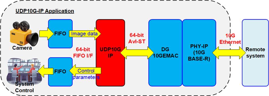
Figure 1: UDP10G IP Application
Figure 1 shows an example application of video camera system, where video raw data from the camera is stored in a FIFO and forwarded to a remote system via 10G Ethernet using the UDP10G IP. The UDP10G IP supports full-duplex transfer simultaneously using different port numbers, allowing the Remote system to update the parameters for real-time controlling via 10G Ethernet while receiving the data from UDP10G IP via 10G Ethernet network.
UDP10G IP is designed to transfer data at the high speed, resulting a latency time that is increased by the internal pipeline register and buffer. For low-latency applications such as FinTech, we recommend the user of our low-latency IP. More details about this IP can be found on our website.
https://dgway.com/Lowlatency-IP_A_E.html
General Description
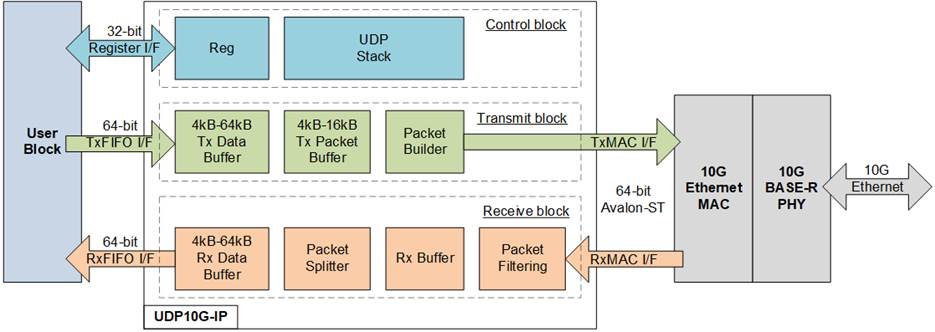
Figure 2: UDP10G IP Block Diagram
The UDP10G IP core is a hardwired logic implementation of the UDP/IP stack that connects with the 10G Ethernet MAC (EMAC) and 10G BASE-R PHY modules to form the low-layer hardware. The user interface of UDP10G IP consists of two interfaces, i.e., the Register interface for control signals and the FIFO interface for data signals.
The Register interface uses a 4-bit address for accessing up to 16 registers, including network parameters, command registers, and system parameters. Bi-directional data transfer is achieved using two sessions for each UDP10G IP, one session assigned for each direction. The network parameters for both sessions must be the same, except the port number on the target device. Network parameters must be set before de-asserting the reset signal to execute IP initialization. After finishing the reset operation and parameter initialization, the IP is ready to transfer data with the target device. Network parameters cannot be changed without a reset process. UDP10G IP has two initialization modes for obtaining the MAC address of the target device. Further details of each mode can be found in the IP Initialization topic.
To transmit UDP payload data, the user is required to configure the total transfer size, packet size, and issue a send command to the IP. Thos UDP payload data is transferred via TxFIFO interface, which operates with a 64-bit data size. Since there is no byte enable in the TxFIFO interface, data sent by the user adheres to a 64-bit alignment. Additionally, both the packet length and the total amount of transmitted data must align with a 64-bit boundary.
Conversely, when the UDP packet is received from the target, the UDP payload data is extracted and stored in the Rx data buffer. The user�s logic continuously monitors the FIFO status to check the quantity of received data, and then asserts the read enable to read data via the RxFIFO interface. Data on the Rx FIFO I/F can only be read when at least one 64-bit data unit is available in the Rx data buffer. In situations where the total amount of received data is not aligned to 64-bit boundary, the user cannot read the last data until the next data arrives to complete the remaining bytes for reading the Rx data buffer.
To meet the user system requirements, which may be sensitive to the memory resources or the performance, the buffer size inside the IP can be assigned by the user. There are three buffers whose sizes can be adjusted, i.e., Tx data buffer, Tx packet buffer, and Rx data buffer. If the Tx buffer size is too small, the UDP10G IP may transmit all data to the target before the user fills the buffer with new data, causing the UDP10G IP to pause transmission and wait for new data from the user. On the other hand, if the Rx buffer size is too small, the buffer may become full if the user pauses reading data from the UDP10G IP for a long time, causing the UDP10G IP to reject the new received packet from the target.
Functional Description
As shown in Figure 2, UDP10G IP can be divided into three blocks - control block, transmit block, and receive block. The details of each block are described as follows.
Control Block
· Reg
All parameters of the IP are set via Register interface that consists of 4-bit address signals and 32-bit data signals. The timing diagram of the Register interface is similar to a single-port RAM interface, as shown in Figure 5. The write and read addresses are the same signal. Table 2 provides a description of each register.
Table 2: Register map Definition
|
RegAddr [3:0] |
Reg Name |
Dir |
Bit |
Description |
|
0000b |
RST |
Wr /Rd |
[0] |
Reset IP. 0b: No reset, 1b: Reset. Default value is 1b. Once the network parameters have been assigned, the user can execute system initialization by setting this register to 1b and then 0b. This action loads the parameters into the IP. If the user needs to update certain parameters, this process must be repeated by setting this register to 1b and then 0b again. The RST register controls the following network parameters: SML, SMH, DIP, SIP, DPN, SPN, and SRV. |
|
0001b |
CMD |
Wr |
[0] |
User command. Set 1b to start sending data. In order to start a new operation by setting this register, the system must first be in the Idle state. To confirm that the system is not busy, the user should read Busy signal or bit[0] of CMD register, which should be equal to 0b. |
|
Rd |
[0] |
System busy flag. 0b: Idle, 1b: IP is busy from initialization or send command. This signal is also mapped as Busy (IP output signal). |
||
|
0010b |
SML |
Wr /Rd |
[31:0] |
Define 32-bit lower MAC address (bit [31:0]) for the host To update this value, the IP must be reset by RST register. |
|
0011b |
SMH |
Wr /Rd |
[15:0] |
Define 16-bit upper MAC address (bit [47:32]) for the host. To update this value, the IP must be reset by RST register. |
|
0100b |
DIP |
Wr /Rd |
[31:0] |
Define 32-bit target IP address. To update this value, the IP must be reset by RST register. |
|
0101b |
SIP |
Wr /Rd |
[31:0] |
Define 32-bit IP address for the host. To update this value, the IP must be reset by RST register. |
|
0110b |
DPN |
Wr /Rd |
[31:0] |
[15:0]-Define 16-bit target port number using for the UDP10G IP to send data. [31:16]-Define 16-bit target port number using for the UDP10G IP to receive data. To update this value, the IP must be reset by RST register. |
|
0111b |
SPN |
Wr /Rd |
[15:0] |
Define 16-bit port number for the host. To update this value, the IP must be reset by RST register. |
|
1000b |
TDL |
Wr |
[31:0] |
Total Tx data length in byte unit. The value must be aligned to 8-byte and bit[2:0] are not used. Valid range is 8-0xFFFFFFF8. The user must first set this register before setting CMD register=1b. When the IP executes the command and asserts Busy to 1b, the system will read this register, allowing the user to subsequently set the TDL register for the next command. If the same TDL is used in the subsequent command, the user is not required to set TDL again. |
|
Rd |
Remaining transfer length in byte unit which does not transmit. |
|
RegAddr [3:0] |
Reg Name |
Dir |
Bit |
Description |
|
1001b |
TMO |
Wr |
[31:0] |
Define timeout value for awaiting the return of an ARP reply packet after sending an ARP request packet. The counter for the timer unit operates at 156.25 MHz, resulting in a timer unit equal to 6.4 ns. If the ARP reply packet is not received in the specified time, IntOut will be asserted to 1b. The optimal value depends on system requirements and network characteristics, but it is typically set to 1 second or larger. |
|
Rd |
The details of timeout interrupt are shown in TMO[0] and TMO[10:8]. [0]-Timeout from not receiving ARP reply packet After timeout, the IP resends ARP request packet until ARP reply packet is received. [8]-Asserted when Rx data buffer is full. After that, all received packet are ignored until the buffer is not full. [9]-Asserted when UDP checksum of the received packet is error. [10]-Asserted when MacRxUser shows error status. |
|||
|
1010b |
PKL |
Wr /Rd |
[15:0] |
UDP data length of one Tx packet in byte unit. The value mast be aligned to 8-byte, and bit[2:0] are not used. Valid from 8-8968. Default value is 1472 bytes, which is the maximum size of non-jumbo frame and aligned to 8-byte. During running Send data command (Busy=1b), the user must not set this register. Similar to TDL register, the user does not need to set PKL register again if the next command uses the same packet length. |
|
1110b |
SRV |
Wr/ Rd |
[0] |
0b: Client mode (default). When the RST register changes from 1b to 0b, the IP sends an ARP request to obtain the Target MAC address from the ARP reply returned by the target device. The IP busy signal is de-asserted to 0b after receiving the ARP reply. 1b: Server mode. When RST register changes from 1b to 0b, the IP waits for an ARP request from the target to obtain Target MAC address. After receiving the ARP request, the IP generates an ARP reply and then de-asserts the IP busy signal to 0b. Note: In Server mode, when RST register changes from 1b to 0b, the target device needs to resend the ARP request for the UDP10G IP to complete the IP initialization process. |
|
1111b |
VER |
Rd |
[31:0] |
IP version |
· UDP Stack
The UDP stack is responsible for controlling the modules involved in interfacing with the user and transferring packets via EMAC. The IP operation involves two phases - IP initialization and data transfer. After the RST register transitions from 1b to 0b, the initialization phase begins. The SRV[0] is used to set the initialization mode, which can be Client mode or Server mode. The UDP stack reads the parameters from the Reg module and sets them in the Transmit and Receive blocks for packet transfer with the target device. Once initialization is completed, the IP enters the data transfer phase.
The UDP10G IP allows for simultaneous data transfer in both Tx and Rx directions with the target device. During sending data, the Busy signal is set to 1b. It is de-asserted to 0b once the sending process is completed. To transmit data, the user data is stored in the Tx data and Tx packet buffers. The Packet Builder uses the user-defined network parameters to build UDP header, and then the data of Tx data buffer is appended to the UDP packet. The Transmit block then sends the UDP packet to the target device via EMAC.
When the Receive block receives data, the Busy signal is not asserted. The extracted UDP payload data from the received packet is forwarded to the user without generating any packet to be returned to the target device. The transmitted and received packets of the UDP/IP are processed separately to achieve optimal performance in both data transfer directions.
Table 3: TxBuf/TxPac/RxBufBitWidth Parameter description
|
Value of BitWidth |
Buffer Size |
TxBufBitWidth |
TxPacBitWidth |
RxBufBitWidth |
|
9 |
4 KB |
Valid |
Valid |
Valid |
|
10 |
8 KB |
Valid |
Valid |
Valid |
|
11 |
16 KB |
Valid |
Valid |
Valid |
|
12 |
32 KB |
Valid |
No |
Valid |
|
13 |
64 KB |
Valid |
No |
Valid |
Transmit Block
· Tx Data Buffer
The size of this buffer is determined by the �TxBufBitWidth� parameter of the IP, with valid value ranging from 9-13, which corresponds to the address size of a 64-bit buffer as shown in Table 3. To ensure sustainable transmission of data to EMAC, the buffer size should be at least twice the size of the Tx Packet Size set in the PKL register. By filling the buffer with data that is at least two times of the PKL value, the UDP10G IP will have a sufficient amount of data to transmit. This results in the best transmit performance on 10G Ethernet. Increasing the size of the buffer increases the possibility that at least two packet data will be available for UDP10G IP use.
· Tx Packet Buffer
The size of the buffer is determined by the �TxPacBitWidth� parameter of the IP. Its valid range is 9-11, and the details of the parameter are shown in Table 3. To store at least one transmit packet, the buffer size must be larger than the Tx packet size set by the PKL register. Note that the maximum value of the PKL register is equal to the Tx Packet Buffer size (in bytes) minus 32. Configuring the buffer size to be greater than two times of PKL value does not provide any additional benefits.
· Packet Builder
The UDP packet is comprised of a header and data. The Packet builder first receives network parameters from the Reg module and uses them to construct the UDP header. The UDP and IP checksum are also calculated for the header. Once the header is fully constructed, it is combined with the data from the Tx packet buffer and then transmitted to the EMAC.
Receive Block
The Receive block contains the Rx data buffer, which stores the data received from the target device. The received data is stored in the buffer when the header in the packet matches the expected value, set by the network parameters inside the Reg module, and when the IP and UDP checksum are correct. If any of these conditions are not met, the received packet is rejected. Increasing the size of the Rx data buffer enhances the chances of avoiding lost packets due to user logic pausing for too long while reading data.
· Rx Buffer
This is temporary buffer that is used to hold incoming packets from EMAC in cases where the previous packet has not yet been completely processed.
· Packet Filtering
This module is responsible for verifying the header of the Rx packet to determine its validity. The packet will be valid if all following conditions are met.
1) The network parameters must match the values set in the Reg module, such as the MAC address, IP address, and Port number.
2) The packet must either be an ARP packet or a UDP/IPv4 packet.
3) The IP header length must be valid, with the IP length being equal to 20 bytes.
4) The IP data length matches to the UDP data length.
5) Both the IP checksum and UDP checksum must be correct.
Note: UDP checksum is not verified for fragment packet.
6) In case of fragment packet, the order of received packet must be correct. The packet is rejected when the fragment offset is skipped value.
· Packet Splitter
· Rx Data Buffer
The size of the Rx data buffer is determined by the �RxBufBitWidth� parameter of the IP and can range from 9 � 13 (4KB to 64KB). It is recommended to set the buffer size to be equal to or greater than two times of the data size in the received packet. To ensure that data is not lost, user logic must read data from the buffer to keep the free space size of the buffer to be greater than the payload data size in the new received packet. Increasing the size of the buffer increases the possibility of having enough free space to store new data from the target device.
User Block
The core engine of the user module can be designed by state machine to set the command and the parameters through the Register interface. Additionally, the status can be monitored to ensure that the operation has been completed without any errors. The data path can also be connected to the FIFO for sending or receiving data with the IP.
10G Ethernet MAC
The 10G EMAC interface with UDP10G IP employs a 64-bit Avalon stream interface, while its interface with the 10G BASE-R PHY utilizes a 64-bit XGMII interface. Design Gateway offers the 10G EMAC IP, which optimizes resource utilization and minimizes data latency when connecting with UDP10G IP. You can find more details about the DG 10G EMAC IP Core on our website.
https://dgway.com/products/IP/10GEMAC-IP/dg_tengemacip_data_sheet_intel_en/
Intel also provides a low latency Ethernet 10G MAC with numerous features, which UDP10G IP can directly connect to. You can find more information about the Intel 10G EMAC FPGA IP on their website.
10G BASE-R PHY
The 10G BASE-R PHY is an IP core by Intel FPGA designed for connectivity with 10G Ethernet MAC via a standard XGMII interface running at 156.25 MHz. This IP core enables direct connection with SFP+ optical module. For additional details, please refer to the following website.
Core I/O Signals
Descriptions of all parameters and I/O signals are provided in Table 4 and Table 5. The EMAC interface is 64-bit Avalon stream standard.
Table 4: Core Parameters
|
Generic Name |
Value |
Description |
|
TxBufBitWidth |
9-13 |
Setting Tx Data buffer size. The value is referred to address bus size of this buffer. |
|
TxPacBitWidth |
9-11 |
Setting Tx Packet buffer size. The value is referred to address bus size of this buffer. |
|
RxBufBitWidth |
9-13 |
Setting Rx Data buffer size. The value is referred to address bus size of this buffer. |
Table 5: Core I/O Signals
|
Signal |
Dir |
Description |
|
Common Interface Signal |
||
|
RstB |
In |
Reset IP core. Active Low. |
|
Clk |
In |
156.25 MHz fixed clock frequency input for user interface and MAC interface of 10G Ethernet. |
|
User Interface |
||
|
RegAddr[3:0] |
In |
Register address bus. In Write access, RegAddr is valid when RegWrEn=1b. |
|
RegWrData[31:0] |
In |
Register write data bus. Valid when RegWrEn=1b. |
|
RegWrEn |
In |
Register write enable. Valid at the same clock as RegAddr and RegWrData. |
|
RegRdData[31:0] |
Out |
Register read data bus. Valid in the next clock after RegAddr is valid. |
|
Busy |
Out |
IP busy status (0b-Idle, 1b-IP is busy when executing the initialization or send data process) |
|
IntOut |
Out |
Timer interrupt. Assert to high for 1 clock cycle when timeout is detected or Rx packet is ignored. More details of Interrupt status could be checked from TMO[10:0] register. |
|
Tx Data Buffer Interface |
||
|
UDPTxFfFull |
Out |
Asserted to 1b when Tx data buffer is full. User needs to stop writing data within 4 clock cycles after this flag is asserted to 1b. |
|
UDPTxFfWrCnt[12:0] |
Out |
Data counter in 64-bit unit of Tx data buffer to show the amount of data in Tx data buffer. |
|
UDPTxFfWrEn |
In |
Write enable to Tx data buffer. Asserted to 1b to write data to Tx data buffer. |
|
UDPTxFfWrData[63:0] |
In |
Write data to Tx data buffer. Valid when UDPTxFfWrEn=1b. |
|
Rx Data Buffer Interface |
||
|
UDPRxFfRdCnt[12:0] |
Out |
Data counter of Rx data buffer to show the number of received data in 64-bit unit. |
|
UDPRxFfLastRdCnt[2:0] |
Out |
Remaining byte of the last data in Rx data buffer when total received data in the buffer is not aligned to 8-byte unit. User cannot read data until all 8-byte data is received. |
|
UDPRxFfRdEmpty |
Out |
Asserted to 1b when Rx data buffer is empty. User needs to stop reading data immediately when this signal is asserted to 1b. |
|
UDPRxFfRdEn |
In |
Asserted to 1b to read data from Rx data buffer. |
|
UDPRxFfRdData[63:0] |
Out |
Data output from Rx data buffer. Valid in the next clock cycle after UDPRxFfRdEn is asserted to 1b. |
|
Signal |
Dir |
Description |
|
MAC Interface |
||
|
MacTxData[63:0] |
Out |
Transmitted data. Valid when MacTxValid=1b. |
|
MacTxEmpty[2:0] |
Out |
Specify the number of bytes which are unused of the final word in the frame. |
|
MacTxValid |
Out |
Valid signal of transmitted data. |
|
MacTxSOP |
Out |
Control signal to indicate the first word in the frame. Valid when MacTxValid=1b. |
|
MacTxEOP |
Out |
Control signal to indicate the final word in the frame. Valid when MacTxValid=1b. |
|
MacTxReady |
In |
Handshaking signal. Set to 1b when MacTxData has been accepted. This signal must not be de-asserted to 0b when a packet is transmitting. |
|
MacRxData[63:0] |
In |
Received data. Valid when MacRxValid=1b. |
|
MacRxValid |
In |
Valid signal of received data. MacRxValid must be asserted to 1b continuously for transferring a packet. |
|
MacRxEOP |
In |
Control signal to indicate the final word in the frame. Valid when MacRxValid=1b. |
|
MacRxError |
In |
Control signal asserted at the end of received frame (MacRxValid=1b and MacRxEOP=1b) to indicate that the frame has CRC error. 1b: error packet, 0b: normal packet. To connect with Intel 10G EMAC, this port connects to avalon_st_rx_error[1] signal. |
|
MacRxReady |
Out |
Handshaking signal. Asserted to 1b when MacRxData has been accepted. MacRxReady is de-asserted to 0b for 1 clock cycles to be the gap size between each received packet. |
Timing Diagram
IP Initialization
After the RST register value is changed from 1b to 0b, the initialization of UDP10G IP is initialized. Two modes can be executed, Client mode (SRV[0]=0b) or Server mode (SRV[0]=1b). The information on each mode is presented in the timing diagram below.
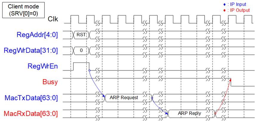
Figure 3: IP Initialization in Client mode
As shown in Figure 3, in Client mode, the UDP10G IP sends an ARP request and waits for an ARP reply packet returned from the target device. Target MAC address is extracted from ARP reply packet. Upon completion, the Busy signal is de-asserted to 0b.

Figure 4: IP Initialization in Server mode
As shown in Figure 4, after reset process in Server mode is completed, the UDP10G IP waits for an ARP request packet from the target device. Upon receipt, the UDP10G IP generates an ARP reply packet. The Target MAC address is extracted from ARP request packet. Once the ARP reply packet has been transmitted, the Busy signal is de-asserted to 0b.
Register Interface
The Register interface is responsible for setting and monitoring all control signals and network parameters during operation. The timing diagram of the interface is similar to that of Single-port RAM, which shares the address bus for write and read access, and has a read latency time of one clock cycle. A Register map of this interface is provided in Table 2.
As shown in Figure 5, to write to the register, the user sets RegWrEn to 1b with the valid values for RegAddr and RegWrData. Before setting RegWrEn to 1b, please confirm that RstB is de-asserted to 1b for at least 4 clock cycles. To read from the register, the user only sets RegAddr, and RegRdData becomes valid in the next clock cycle.
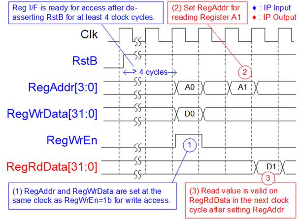
Figure 5: Register interface timing diagram
As shown in Figure 6, before setting the CMD register to initiate a new command operation, the Busy flag must be equal to 0b to confirm that IP is in Idle status. After setting the CMD register, the Busy flag is asserted to 1b and de-asserted to 0b when the command is completed.
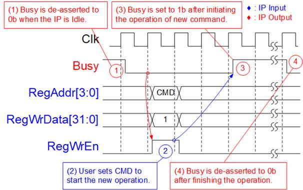
Figure 6: CMD register timing diagram
Tx FIFO Interface
Tx FIFO interface provides two control signals for the flow control, the full flag (UDPTxFfFull) and the write data counter (UDPTxFfWrCnt). UDPTxFfWrCnt is updated after asserting UDPTxFfWrEn for two clock cycles. UDPTxFfFull serves as an indicator of when the internal buffer is almost full and is asserted before it reaches its capacity. It is recommended to pause sending data within four clock cycles after UDPTxFfFull is asserted. Figure 7 shows an example timing diagram for the Tx FIFO interface.
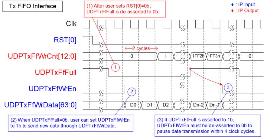
Figure 7: Tx FIFO interface timing diagram
1) When the IP is in reset state (RST[0] register=1b), the full flag (UDPTxFfFull) is set to 1b, preventing data from being sent by the user. Once the reset is de-asserted (RST[0]=0b), UDPTxFfFull is set to 0b, allowing the user to write data to the IP.
2) To write data, the user needs to set UDPTxFfWrEn to 1b along with the write data on UDPTxFfWrData signal.
3) If UDPTxFfFull is set to 1b, the user must pause sending data by de-asserting UDPTxFfWrEn to 0b within 4 clock cycles.
Rx FIFO Interface
The Rx FIFO interface is used to retrieve data stored in the Rx data buffer. To determine if data is available for reading, the Empty flag (UDPRxFfEmpty) is monitored, and the read enable signal (UDPRxFfRdEn) is then asserted to access the data, like a typical FIFO read interface, as illustrated in as shown in Figure 8.
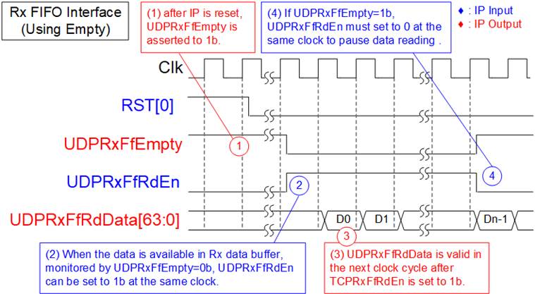
Figure 8: Rx FIFO interface timing diagram using Empty flag
1) After the completion of the IP reset process, there is no data in Rx data buffer. Consequently, UDPRxFfEmpty is set to 1b.
2) Check the UDPRxFfEmpty flag to confirm data availability. When data is available (UDPRxFfEmpty=0b), set UDPRxFfRdEn to 1b to read data from the Rx data buffer.
3) The UDPRxFfRdData signal is valid in the next clock cycle.
4) Reading data must be immediately paused by setting UDPRxFfRdEn=0b when UDPRxFfEmpty is equal to 1b.
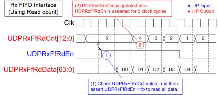
Figure 9: Rx FIFO interface timing diagram using read counter
When the user logic reads data in burst mode, the UDP10G IP provides a read data counter signal to indicate the total amount of data stored in the Rx data buffer in bytes. For instance, in Figure 9, there are five units of data available in the Rx data buffer. Therefore, the user can set UDPRxFfRdEn to 1b for five clock cycles to read all the data from the Rx data buffer. The latency time to update UDPRxFfRdCnt after setting UDPRxFfRdEn to 1b is two clock cycles.
EMAC Interface
EMAC interface of UDP10G IP utilizes a 64-bit Avalon-stream interface, but it has a limitation that it cannot pause data transmission before transmitting the end of the packet. To transmit a packet, the MacTxReady must be asserted to 1b while transmitting a packet. However, once the final data of the packet has been transferred, MacTxReady can be de-asserted to 0b to pause the transmission of the next packet.
Figure 10: Transmit EMAC Interface timing diagram
1) UDP10G IP asserts both MacTxSOP and MacTxValid to 1b with the first data of the packet. All signals are latched until MacTxReady is asserted to 1b to accept the first data.
2) After the first data is accepted by EMAC, MacTxReady must remain set to 1b to accept all remaining data in the packet from the UDP10G IP until the end of the packet. The IP sends all data of each packet continuously.
3) MacTxEOP and MacTxValid are both asserted to 1b when the last data of the packet is transmitted.
4) After the end of the packet has been transferred, MacTxReady can be asserted to 0b to pause the transmission of the next packet.
The Receive EMAC interface also requires continuous receipt of packet data, similar to Transmit EMAC interface. The Valid signal must remain asserted at 1b from the start of the packet to the end of the packet without interruption, as shown in Figure 11.
Figure 11: Receive EMAC interface timig diagram
1) The UDP10G IP detects the start of the receive frame when MacRxValid changes from 0b to 1b. In this cycle, the first data is valid on MacRxData. Afterward, MacRxReady is asserted to 1b to accept all data of this packet until the end of the packet. To continuously send the data of each packet, MacRxValid must remain set to 1b.
2) The end of the packet is detected when MacRxEOP=1b and MacRxValid=1b. In this cycle, the final data of the packet is valid on MacRxData.
3) After the final data of the packet has been transferred, UDP10G IP de-asserts MacRxReady for 1 clock cycle to complete the packet post-processing. Therefore, EMAC must support pausing data packet transmission for 1 clock cycle.
Example usage
Client mode (SRV[0]=0b)
The steps to set the register for transferring data in Client mode are outlined below.
1) Set the RST register=1b to reset the IP.
2) Set the SML/SMH for MAC address, DIP/SIP for IP address, and DPN/SPN for port number.
3) Set RST register=0b to start the IP initialization process. The UDP10G IP will send an ARP request packet to get the Target MAC address from the ARP reply packet. The Busy signal is de-asserted to 0b after completing the initialization process.
4) a. For sending data, set TDL register (total transmit length) and PKL register (packet size). Then, set CMD register = 1b to start data transmission. The user can send data to UDP10G IP via the TxFIFO interface before or after setting the CMD register. Once the command is finished, the Busy flag is de-asserted to 0b. The user can set a new value to the TDL/PKL register and then set CMD register = 1b to start the next transmission.
b. For receiving data, the user should monitor RxFIFO status and read data until RxFIFO is empty.
Server mode (SRV[0]=1b)
In Server mode, the MAC address is decoded from ARP request packet instead of ARP reply packet as in Client mode. However, the process for transferring data is the same as that of Client mode. The following steps illustrate an example of Server mode.
1) Set RST register=1b to reset the IP.
2) Set SML/SMH for MAC address, DIP/SIP for IP address, and DPN/SPN for port number.
3) Set RST register=0b to begin the IP initialization process by waiting for an ARP request packet to get the Target MAC address. The IP then creates an ARP reply packet to return to the target device. Once the initialization process is completed, the Busy signal is de-asserted to 0b.
4) The remaining steps are the same as steps 4 of Client mode
Verification Methods
The UDP10G-IP Core functionality was verified by simulation and also proved on real board design by using Arria10 GX/Arria10 SoC development board.
Recommended Design Experience
User must be familiar with HDL design methodology to integrate this IP into system.
Ordering Information
This product is available directly from Design Gateway Co., Ltd. Please contact Design Gateway Co., Ltd. For pricing and additional information about this product using the contact information on the front page of this datasheet.
Revision History
|
Revision |
Date |
Description |
|
1.3 |
17-Oct-23 |
Add UDPTxFfWrCnt signal, update PKL range, and update Figure5. |
|
1.2 |
2-Oct-20 |
Update company info |
|
1.1 |
22-Mar-18 |
Support A10 SoC |
|
1.0 |
19-Sep-17 |
New release |