FPGA Setup for NVMeG4-IP with DMA on PetaLinux
1 Overview
This document outlines the necessary setup procedures for running the NVMeG4-IP with DMA demo on a PetaLinux, based on FPGA development board. The demonstration involves connecting an NVMe Gen4 SSD via an adapter board and interacting with the system through a Serial console on a PC. In this setup, the FPGA is both booted and configured using an SD card that contains the required boot and operating system files.
2 Environment Requirements
To successfully run the demo, ensure the following hardware and software components are prepared:
1) Supported FPGA development board: ZCU106.
2) PCIe adapter board: AB17-M2FMC, provided by Design Gateway:
https://dgway.com/ABseries_E.html
3) An M.2 NVMe Gen4 SSD (or higher) installed on the PCIe adapter board.
4) Serial console software (e.g., TeraTerm) installed on PC, with the following settings: Baud rate=115,200; Data=8-bit; Parity=None; and Stop bits=1-bit.
5) Power adapter for the FPGA development board.
6) A micro-USB cable for Serial console connection.
7) An SD card containing the necessary files: boot loader
(BOOT.BIN) and Linux image (image.ub), downloaded from: https://dgway.com/NVMe-IP_X_E.html
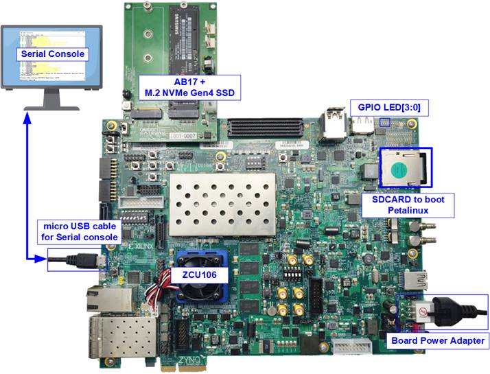
Figure 1 Demo Setup on ZCU106 with
AB17
3 Demo Setup
1) Ensure that the power switch on the FPGA board is turned OFF.
2) The SD card must be formatted with the FAT32 file system. Copy the following three files to the root directory of the card: “BOOT.BIN”, “boot.scr”, and “image.ub”.
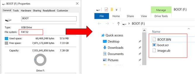
Figure 2 Copy SD Card Image
3) Insert the SD card into the SD card socket on the FPGA board.
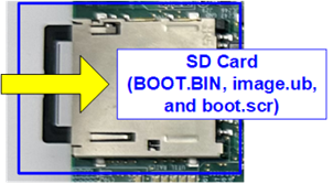
Figure 3 SD Card Setup
4) On the FPGA board, set SW6[1:4] = [ON OFF OFF OFF] to enable the FPGA to load its configuration from the SD card.
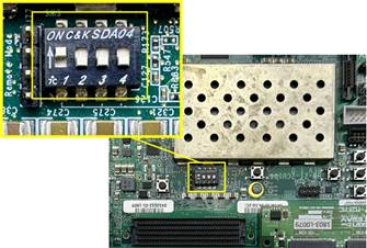
Figure 4 SW6 Setting for FPGA Configuration by SD Card (ZCU106)
5) Prepare the NVMe Gen4 SSD and AB17-M2FMC PCIe Adapter board.
i) Connect the M.2 NVMe Gen4 SSD to Drive#1 M.2 connector on the AB17-M2FMC board.
ii) Connect the AB17-M2FMC board to the HPC0 connector (J5) on the ZCU106 board, as shown in Figure 5.
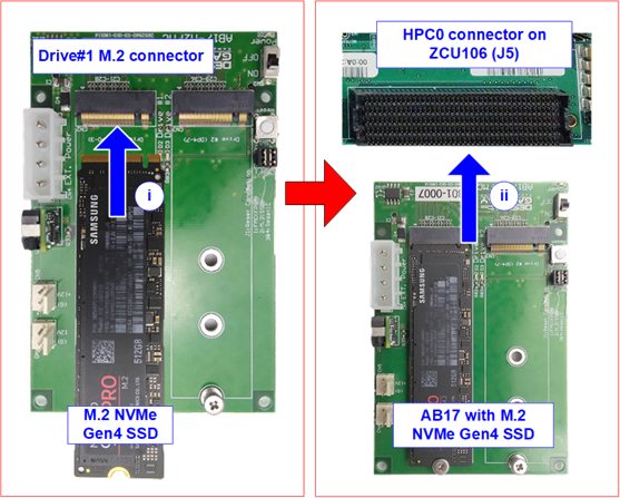
Figure 5 Setup AB17-M2FMC and SSD
6) Connect a micro-USB cable from the FPGA board to the PC to enable serial communication. After connecting USB cable, the new COM ports appear. Select the first interface listed among the newly detected COM ports.
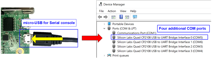
Figure 6 Insert Micro-USB Cable and Detect Additional COM Ports
7) Open serial console and configure the console with the following parameters: Baud rate=115,200, Data=8 bits, Parity=None, and Stop bits= 1, as shown in Figure 7.
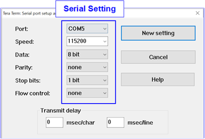
Figure 7 Serial Console Setting
8) Power on the system.
i) Turn on the power switch on the PCIe adapter board.
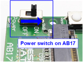
Figure 8 Power Switch on PCIe Adapter Board
ii) Turn on the power switch on the FPGA development board.
9) After the initialization process is complete, check the status of the onboard LEDs to confirm successful boot-up. Refer to Table 1 for detailed LED status information.
Table 1 LED Definition
|
GPIO LED |
ON |
OFF |
|
0 |
Normal operation |
Clock is not locked or reset button is pressed |
|
1 |
System is busy |
Idle status |
|
2 |
IP error detected |
Normal operation |
|
3 |
PCIe link up |
No PCIe Link |
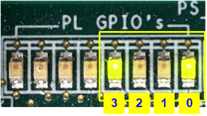
Figure 9 LED Status After
Initialization Completes
10) On the PC’s serial console, wait until the PetaLinux finishes booting and the login prompt appears, as shown in Figure 10.
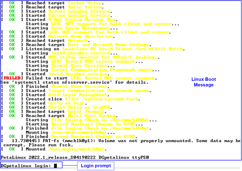
Figure 10 Linux Bootup
4 Revision History
|
Revision |
Date (D-M-Y) |
Description |
|
1.00 |
14-May-25 |
Initial version release |