TOE10G-IP Core Datasheet
· Parameter Registers (Param Regs)
10G Ethernet PCS/PMA (10GBASE-R)
PKL and TDL setting in Send command
TDL = N times of PKL + Residue
Connection Termination and Unusual Case

Core Facts |
|
|
Provided with Core |
|
|
Documentation |
User Guide, Design Guide |
|
Design File Formats |
Encrypted File |
|
Instantiation Templates |
VHDL |
|
Reference Designs & Application Notes |
Vivado Project, See Reference Design Manual |
|
Additional Items |
Demo on KC705/VC707/ZC706/ KCU105/ZCU102/ZCU106/VCU118 |
|
Support |
|
|
Support Provided by Design Gateway Co., Ltd. |
|
Design Gateway Co.,Ltd
E-mail: ip-sales@design-gateway.com
URL: www.design-gateway.com
Features
· Comprehensive TCP/IP offloading engine eliminating the need for CPU or DDR
· Support IPv4 protocol without IP fragmentation
· Support single TCP session (multiple sessions require multiple TOE10G IPs)
· Support Jumbo frame
· Configurable TCP buffer size: Up to 64 KB, optimizing resource utilization and performance
· User control I/F: Single-port RAM with a 32-bit data bus
· User data I/F: FIFO interface with a 64-bit data bus, devoid of byte enable (requires 64-bit alignment)
· Required alignment of transmitted packet size at 64 bits
· Retrieval of received data possible upon reaching a minimum of 64 bits
· Ethernet MAC I/F: AXI4-ST with a 64-bit data bus
· Operation within a single clock domain at 156.25 MHz (output from Ethernet MAC)
· Reference design available on KC705/VC707/ZC706/KCU105/ZCU102/ZCU106/VCU118 boards
· Customized options for the following features
· Unaligned 64-bit data transfer
· Buffer size extension using Windows Scaling feature
· Support for the Ping command or DHCP
Table 1: Example Implementation Statistics for 7-Series device
|
Family |
Example Device |
Fmax (MHz) |
Slice Regs |
Slice LUTs |
Slice1 |
BRAMTile2 |
Design Tools |
|
XC7K325TFFG900-2 |
156.25 |
3,140 |
3,600 |
1,265 |
36 |
Vivado2023.2 |
|
|
Zynq-7000 |
XC7Z045FFG900-2 |
156.25 |
3,140 |
3,601 |
1,301 |
36 |
Vivado2023.2 |
|
Virtex-7 |
XC7VX485TFFG1761-2 |
156.25 |
3,101 |
3,601 |
1,294 |
36 |
Vivado2023.2 |
Table 2: Example Implementation Statistics for Ultrascale device
|
Family |
Example Device |
Fmax (MHz) |
CLB Regs |
CLB LUTs |
CLB1 |
BRAMTile2 |
Design Tools |
|
Kintex-Ultrascale |
XCKU040FFVA1156-2E |
156.25 |
3,146 |
3,674 |
740 |
34.5 |
Vivado2023.2 |
|
Zynq-Ultrascale+ |
XCZU9EG-FFVB1156-2-I |
156.25 |
3,146 |
3,662 |
708 |
34.5 |
Vivado2023.2 |
|
Virtex-Ultrascale+ |
XCU9P-FLGA2104-2L |
156.25 |
3,174 |
3,658 |
731 |
34.5 |
Vivado2023.2 |
Notes:
1) Actual logic resource dependent on percentage of unrelated logic
2) Block RAM resources are based on 64KB Tx data buffer size, 16KB Tx packet buffer size, and 64KB Rx data buffer size which are maximum buffer size to achieve the best performance.
Applications
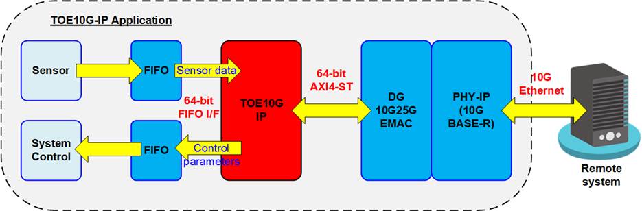
Figure 1: TOE10G IP Application
10G Ethernet serves as the communication channel for transferring high-speed data with remote controlling system. When combined with the TCP/IP protocol, this system can ensure reliable data transfer at high-speed performance. TOE10G IP is an integrated IP that enables data transfer via 10G Ethernet without requiring the use of CPU or external memory. It is suitable for applications that require high-speed data transfer, such as video data streaming and sensor monitoring system using FPGA solutions.
Figure 1 shows an example of a sensor monitoring system, where data from the sensor is stored in a FIFO and forwarded to a remote system via 10G Ethernet by TOE10G IP. The TOE10G IP supports full-duplex transfer in the same TCP session, allowing the remote system to send parameters for controlling the sensor monitoring system via 10G Ethernet. Our website also offers an FTP server demo that utilizes the TOE10G IP and NVMe IP. For more information about this demo, please contact us.
TOE10G IP is designed to transfer data at high speed, resulting a latency time that is increased by the internal pipeline registers and buffers. For low-latency application such as FinTech, we recommend the user of our low-latency IP. More details about this IP can be found on our website.
https://dgway.com/Lowlatency-IP_X_E.html
General Description
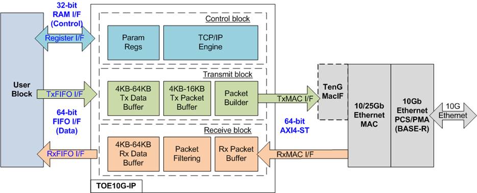
Figure 2: TOE10G IP Block Diagram
The TOE10G IP core serves as a complete offloading engine designed for processing TCP/IP packets. It provides two distinct user interfaces: Control and Data, facilitating the transfer of TCP payload data within a single TCP session. Both Tx and Rx data buffers are configurable independently to accommodate the specific characteristics of each transfer direction. The TOE10G IP utilizes a 64-bit AXI4-ST interface for Ethernet packet transfer to and from the Ethernet MAC.
The TOE10G IP�s logic can be categorized into three main blocks: Control block, Transmit block, and Receive block. The Control block interfaces with the Control I/F, employing a single RAM interface that shares 5-bit address signals for writing and reading 32-bit register data. This block is responsible for configuring commands, managing network parameters, and monitoring the operational status of the IP. Within the Control block, the user parameters are stored at Param Regs. The command requested by user is managed by the TCP/IP engine, enabling the handling of a single TCP session�s TCP/IP stack.
The Transmit block manages the TxFIFO I/F, facilitating the transmission of TCP payload data through a 64-bit FIFO interface without a byte enable signal. Consequently, data transmission always aligns in 64-bit units. User parameters, including transmit packet length and total transmitted data size, must also align in 64-bit units. Data received from the user interface is stored in the Tx data buffer. When a user requests data transmission, TCP payload data is segmented and stored in the Tx packet buffer, later retrieved by the Packet builder to construct TCP/IP packets for transmission to the Ethernet MAC.
Conversely, the Receive block manages the RxFIFO I/F, acquiring TCP payload data from the Ethernet MAC and transmitting it to user via a 64-bit FIFO interface without a byte enable signal. Consequently, the user can access data when at least one 64-bit data is available in the Rx data buffer. In cases where received data is not aligned to 64 bits, the user must await the arrival of the next data to fill the remaining byte of 64-bit data for reading the Rx data buffer.
For additional details about each submodule within the TOE10G IP, please refer to the following section.
Functional Description

Figure 3 TOE10G IP Functional Diagram
In Figure 3, the TOE10G IP�s state diagram illustrates the functionality during operation. Also, the read value of bits[3:1] of CMD register assigned in each state is shown. The details of each state are as follows.
1. Reset: Upon powering on, the default state of the TOE10G IP is the �Reset� state. In this state, it awaits user configuration of network parameters for both the host and the target, including host MAC address (SML and SMH), target MAC address (DML and DMH for Fixed MAC mode), IP addresses (SIP for host, DIP for target), port number (SPN for host, DPN for target), and initialization mode (SRV). Once parameters are set, the user de-asserts RstB to 1b to initialize the target.
2. Target Initialization: The TOE10G IP obtains the MAC address of the target and stores the user-defined network parameters in internal registers (Param Regs). There are three initialization modes, determined by SRV register, for acquiring the target�s MAC address: Client (generating ARP request packet), Server (waiting for ARP reply packet), and Fixed MAC (user-defined value). Once the target�s MAC address is successfully obtained, the initialization process is completed, indicated by the TOE10G IP�s Busy signal being de-asserted to 0b.
3. Target Ready: After successful target initialization, the TOE10G IP awaits a SYN packet transmission to initiate connection establishment.
4. Passive/Active Open: The connection creation involves a three-way handshake process using SYN, SYN-ACK, and ACK packets. The first SYN packet can be sent by either the TOE10G IP (active open) or the target (passive open). Another device responds with a SYN-ACK packet if it accepts the connection request. Finally, the process is completed when the first device that initiated the SYN packet sends an ACK packet. Once the connection is successfully established, indicated by the �ConnOn� signal being set to 1b, the TOE10G IP becomes ready for data transfer.
5. Connection Ready: The TCP protocol facilitates bidirectional data transfer, allowing for the simultaneously transmission and reception of data within the same session. This is achieved by assigning unique sequence and acknowledge numbers for each data transfer direction to indicate the position of transmitted and accepted data. However, Figure 3 illustrates the separate representation of �Send data� and �Receive data� to show the fundamental concept of the TOE10G IP�s functionality.
6. Send Data: A 64-bit FIFO interface is dedicated for transmitting 64-bit data from user to the target in TCP/IP packet format. The sequence number of the transmitted TCP packet is updated after data is sent from the Tx packet buffer to the target. The data is removed from the Tx data buffer once the target updates the acknowledge number of the received TCP packet to confirm the amount of successful received data. If all data is successfully transmitted, the state returns to the �Connection Ready� state. If the session is terminated, the Tx data buffer is automatically flushed.
7. Receive Data: The data received from the target is stored in the Rx data buffer. In accordance with the TCP protocol, the available space in the Rx data buffer corresponds to the received Window size specified in the transmitted TCP packet. This allows the target to continuously send data to the TOE10G IP without waiting for an updated acknowledge number until the total unconfirmed data matches the Window size. While receiving data, the sequence number of received TCP packet is monitored to ensure the correctness of the received data sequence. If any data is lost during this process, triggering packet retransmission occurs. Once the Rx data buffer is completely filled with data, the TOE10G IP generates a packet to update the acknowledge number, which is then sent back to the target. The Rx data buffer is automatically cleared during the connection establishment process. Users can read data within the Rx data buffer through the 64-bit FIFO interface.
8. Passive/Active Close: The connection can be terminated either by the TOE10G IP (active close) or the target (passive close). The first packet used to initiate connection termination is the FIN packet. If termination request is accepted by another device, it responds with FIN and ACK packets, which can be transmitted in single or multiple packets. Finally, the initiating device sends an ACK packet to complete the process. Upon the successful termination, the TOE10G IP state transitions back to �Target Ready� state.
The three distinct blocks (Control, Transmit, and Receive) are responsible for specific functions, as outline below.
Control Block
· Parameter Registers (Param Regs)
The parameters stored in Param Regs can be configured from the user assignment or retrieved from the Receive block. The user-defined parameters include both the host and the target network settings, such as the MAC address, the IP address, and the port number. These configurations are managed via the 32-bit Register I/F, aligning its timing diagram with a Single-port RAM I/F, using the same addresses for both write and read accesses (refer to Figure 4 for details).
The parameters decoded within the Receive block focus on the target network parameters. These includes the MAC address acquired through ARP packet transfer and the port number acquired through passive open operation. The configuration parameters and IP status are allocated to specific register addresses, as explained in Table 3.
Table 3: Register Map Definition
|
RegAddr [4:0] |
Reg Name |
Dir |
Bit |
Description |
|
00000b |
RST |
Wr /Rd |
[0] |
Setting this signal to 1b activates the reset function for the IP core. Upon power-up, its default state is set to 1b. Users can trigger the IP initialization process by changing this register from 1b to 0b. However, before de-asserting this register to 0b, it is crucial for the values within the SML, SMH, DML, DMH, DIP, SIP, DPN, SPN, and SRV registers to remain stable and unchanged until the IP is reset. |
|
00001b |
CMD |
Wr |
[1:0] |
The command register serves to trigger IP operations. Before initiating a new operation, it requires the IP to be in an Idle state, indicated by the �IP Busy� flag set to 0b. This register defines three commands using bits[1:0]. 00b: Send data Before issuing this command, ensure that the �ConnOn� signal is asserted to 1b. Once activated, the IP loads the transmitted packet size from the PKL register and the total transmitted size from the TDL register. Data from the Tx data buffer is sent to the target until all data is successfully transmitted. Additional transmitted size can be configured via the ETL register. Completion of this operation is tracked by the �IP Busy� flag changing from 1b to 0b. 01b: Undefined 10b: Active open The IP initiates the connection establishment by sending a SYN packet. Before issuing this command, ensure that the �ConnOn� signal is de-asserted to 0b. Upon successful connection establishment, the �ConnOn� signal is set to 1b, the �IP Busy� flag changes from 1b to 0b, and the Rx data buffer flushes all data. |
|
RegAddr [4:0] |
Reg Name |
Dir |
Bit |
Description |
|
00001b |
CMD |
Wr |
[1:0] |
11b: Active close The IP initiates the connection termination by sending a FIN packet. Before issuing this command, verify that the �ConnOn� signal is set to 1b and there is no remaining data in the Tx data buffer, indicated by TCPTxFfWrCnt being equal to zero. Successful termination results in the �ConnOn� signal set to 0b, the �IP Busy� flag changing from 1b to 0b, and flushing all data in the Tx data buffer. Note: The �IP Busy� flag can be monitored by two ways: reading bit[0] of this register or bit[0] of RegDataA1, which is the IP output signal. |
|
Rd |
[0] |
The �IP busy� flag. It is set to 1b when the IP is operating, triggered by the user or the target. The information regarding the ongoing IP operation can be retrieved from bits[3:1] of this register. |
||
|
[3:1] |
Indicate the current IP operation or IP�s state, referred to the red text in Figure 3. 000b: Send data The IP enters this state when the user sets �Send data� command. It remains in this state until all data is successfully transmitted to the target. Afterward, the IP transitions to Idle state (001b). 001b: Idle The IP is in an idle condition, ready to receive operation requests from the host or the target. 010b: Active open The IP enters this state when the user sets �Active open� command. It remains in this state until the connection establishment is completed. Afterward, the IP transitions to Idle state. 011b: Active close The IP enters this state when the user sets �Active close� command. It remains in this state until the connection termination is completed. Afterward, the IP transitions to Idle state. 100b: Receive data The IP enters this state upon receiving data from the target during Idle state. It generates a response for data acknowledgement. Afterward, the IP returns to Idle state. 101b: Initialization This state occurs during IP reset or when transferring ARP packets for IP initialization. The IP remains in this state until the IP initialization process is completed. Afterward, the IP transitions to Idle state with setting �IP Busy� to 0b. 110b: Passive open The IP enters this state when the target sends a �SYN� packet to initiate the connection establishment, and the �ConnOn� signal remains at 0b. If the packet contains correct network parameters, the IP responds to accept the request. Upon completion, it returns to Idle state, setting �ConnOn� signal to 1b and clearing all data in the Rx data buffer. 111b: Passive close The IP enters this state when the target sends a �FIN� packet to terminate the connection, and the �ConnOn� signal is at 1b. If the packet contains correct network parameters, the IP responds to accept the request. After completion, it returns to Idle state, setting �ConnOn� signal to 0b and clearing all data in the Tx data buffer. In case of receiving a �FIN� packet during the �Send data� state, the �Send data� command halts to accept the target�s termination. Upon completion, all data in the Tx data buffer is cleared. Users can monitor the completion of the �Send data� command by reading the �TDL� register value. A read value of zero indicates the completion without interruption. Otherwise, a non-zero value shows the remaining transmitted size. |
|
RegAddr [4:0] |
Reg Name |
Dir |
Bit |
Description |
|
00010b |
SML |
Wr /Rd |
[31:0] |
Define 32-bit lower MAC address (bit [31:0]) for the host. This value must not be updated after setting RST register to 0b to start the IP operation. |
|
00011b |
SMH |
Wr /Rd |
[15:0] |
Define 16-bit upper MAC address (bit [47:32]) for the host. This value must not be updated after setting RST register to 0b to start the IP operation. |
|
00100b |
DIP |
Wr /Rd |
[31:0] |
Define 32-bit IP address for the target. This value must not be updated after setting RST register to 0b to start the IP operation. |
|
00101b |
SIP |
Wr /Rd |
[31:0] |
Define 32-bit IP address for the host. This value must not be updated after setting RST register to 0b to start the IP operation. |
|
00110b |
DPN |
Wr /Rd |
[15:0] |
Define 16-bit port number for the target. When the connection is established via passive open, the Receive block extracts port number obtained from the target side and stores it in this register. To operate in active open mode with a new target port number, the user must first set this register to the desired value and keep it stable. Afterwards, the RST register must be activated, and IP initialization must proceed as the next steps. |
|
00111b |
SPN |
Wr /Rd |
[15:0] |
Define 16-bit port number for the host. This value must not be updated after setting RST register to 0b to start the IP operation. |
|
01000b |
TDL |
Wr |
[31:0] |
Configure the total transmitted size in byte units, aligning to 64 bits or 8 bytes. Therefore, bits[2:0] in this register is discarded. Its valid range spans from 8 to FFFF_FFF8h. Set this register before initiating the �Send data� command operation via the CMD register. After initiating the operation, users can update the TDL value for subsequent command. If a new �Send data� command is activated without modifying the TDL register, the IP uses the most recent value from the previous �Send data� command. For transmitted sizes exceeding 4 GB, user can configure additional transmitted size by setting the supplementary value in the �ETL� register. For detailed information, refer to the �ETL� register description. |
|
Rd |
Indicate the remaining transmitted size in byte units. |
|||
|
01001b |
TMO |
Wr |
[31:0] |
Configure timeout value for awaiting the return of received packet from the target. The counter for the timer unit operates at 156.25 MHz, resulting in a timer unit equal to 6.4 ns. If the packet is not received within the specified time, TimerInt will be asserted to 1b. For further information of TimerInt, please refer to the Read value of TMO[7:0] register. The optimal value depends on system requirements and network characteristics, but it is typically set to 1 second or larger. |
|
Rd |
Indicate the interrupt status and the IP status. [7:0] � Timeout interrupt status [0] � Timeout while awaiting an ARP reply packet during initialization in Client mode. The IP retries sending an ARP request packet to the target until an ARP reply packet is received. [1] � Timeout while awaiting a SYN-ACK packet during an active open command. The IP retransmits a �SYN� packet up to 16 times. After the 16th retransmission, The IP sends a �FIN� packet. [2] � Timeout while awaiting an ACK packet during passive open operation. The IP retransmits a SYN-ACK packet up to 16 times. After the 16th retransmission, the IP sends a �FIN� packet. [3] � Timeout while awaiting FIN and ACK packets during active close command. The IP transmits a �RST� packet upon timeout detection. [4] � Timeout while awaiting ACK packet during passive close operation. The IP retransmits FIN and ACK packets up to 16 times. After the 16th retransmission, the IP sends a �RST� packet. [5] � Timeout while awaiting ACK packet during data transmission. The IP retransmits data packet up to 16 times. After the 16th retransmission, the IP sends a �FIN� packet. |
|
RegAddr [4:0] |
Reg Name |
Dir |
Bit |
Description |
|
01001b |
TMO |
Rd |
[31:0] |
[6] � Interrupt triggered by detecting lost received data. The IP generates duplicate ACK packets to request the retransmission of lost data. [7] � Timeout while awaiting a sufficient window size from the target to continue data transmission with bit[2] of PSH register being set to 1b. In response, the IP retransmits 8-byte data packet to prompt the target to return an ACK packet, updating the window size value. After the 16th retransmission without receiving ACK packets, the IP sends a �FIN� packet. [20:8] - Reserved [31:21] � IP status [21] � Asserted to 1b when the received ACK packet contains a skipped sequence number, indicating lost data. [22] � Asserted to 1b upon receiving a �FIN� packet while the �Send data� command is executing. [23] � Asserted to 1b when the received packet contains data size exceeding the remaining window size of Rx data buffer (Fatal error). [26:24] � Internal test status [27] � Asserted to 1b when the received data packet contains a skipped sequence number, indicating lost data. [29:28] � Internal test status [30] � Asserted to 1b when the RST flag of the received packet is set to 1b. [31] � Internal test status |
|
01010b |
PKL |
Wr /Rd |
[15:0] |
Configure the transmitted packet size in byte units, aligning to 64 bits or 8 bytes. Therefore, bits[2:0] in this register is discarded. Its valid range spans from 8 to 8960. The default value is set to 1456 bytes, the maximum size of a non-jumbo frame packet aligning to 8 bytes. This value must not exceed the Maximum Segment Size (MSS) of the target system. Also, it must not be updated while executing the �Send data� command. Similar to TDL register, if a new �Send data� command is activated without modifying the PKL register, the IP uses the most recent value from the previous �Send data� command. |
|
01011b |
PSH |
Wr /Rd |
[2:0] |
Configure the transmission mode during �Send data� command execution. [0] � Configure packet retransmission for the last data packet. 0b (Default): Generate the last data packet twice for the �Send data� command when the TDL value does not align with the PKL value. The duplicated data packet accelerates the target responds an ACK packet, thereby completing the �Send data� command. 1b: Disable the duplicated last data packet. [1] � Configure PSH flag value for transmitted packet. 0b (Default): PSH flag disabled. [2] � Enable timeout triggered by insufficient window size 0b (Default): Disable the feature. 1b: Enable this bit to initiate the timeout triggered by an insufficient window size from the target causing a pause in data transmission. Further details after triggering are described in the read value of bit[7] of TMO register. |
|
[4:0] |
Reg Name |
Dir |
Bit |
Description |
|
01100b |
WIN |
Wr /Rd |
[5:0] |
Configure the threshold value, measured in 1KB units, to determine when the �TCP Window Update� packet is sent to the target. It is valid within the range of 0 to 63. The default value is 0, indicating that this feature is disabled. It becomes enabled when other values are set. It is recommended to be configured to one-fourth of the Rx data buffer size. During receiving data from the target, the IP generates ACK packet containing the window size. If the remaining window size is insufficient, the target temporarily halts data transmission until the window size increases. Once the user reads data and the expanded size of the Rx data buffer reaches or surpasses this threshold value, the IP transmits a �TCP Window Update� packet to update the window size. Upon detecting adequate free space, the target resumes transmitting the next data. |
|
01101b |
ETL |
Wr |
[31:0] |
Configure an additional value to extend the total transmitted size in byte units when the total transmitted size exceeds 4GB (the maximum value of TDL register). This value must align to 64 bits or 8 bytes, so bits[2:0] in this register is discarded. There are two considerations for setting ETL register. 1) Verify that the read value of TDL exceeds double the size of the Tx data buffer to ensure that the operation is not completed before setting ETL register. 2) The set value of ETL must be less than the maximum value of TDL (0xFFFFFFF8) minus the read value of TDL to avoid overflow value. For example, if the user sets TDL = 4 GB and initiates �Send data� command. After transferring 3 GB of data completely, the read value of TDL register equals 1 GB. Next, the user sets ETL register to 2 GB to extend total transmitted size. This results in a total transmitted size of 6 GB (4 GB of TDL + 2 GB of ETL). This process can be repeated by rechecking TDL value and adjusting the ETL register until reaching the required total transmitted size. |
|
01110b |
SRV |
Wr/ Rd |
[1:0] |
Define the options for obtaining the MAC address of the target, with additional details provided in Figure 5 � Figure 7. 00b: Client mode (Default) In this mode, the IP generates an ARP request packet during IP initialization and the target MAC address is extracted from the received ARP reply packet. 01b: Server mode In this mode, the IP awaits an incoming ARP request packet during IP initialization, and the target MAC address is extracted from the received ARP request packet. 1Xb: Fixed MAC mode In this mode, the target MAC address is defined by user through the DML and DMH registers, and loaded by the IP during the initialization process. No ARP exchange requires. This mode must be applied if the host and the target are located on different network. In such cases, the MAC address of the gateway must be set to DML and DMH registers. Note: This value must not be updated after setting RST register to 0b to start the IP operation. |
|
01111b |
VER |
Rd |
[31:0] |
IP version |
|
10000b |
DML |
Wr /Rd |
[31:0] |
Define 32-bit lower MAC address (bit [31:0]) for the target. This register can be accessed only when SRV[1]=1b (Fixed MAC). This value must not be updated after setting RST register to 0b to start the IP operation. |
|
10001b
|
DMH |
Wr /Rd |
[15:0] |
Define 16-bit upper MAC address (bit [31:0]) for the target. This register can be accessed only when SRV[1]=1b (Fixed MAC). This value must not be updated after setting RST register to 0b to start the IP operation. |
· TCP/IP Engine
The TCP/IP engine is responsible for coordinating the execution of each IP function, as shown in Figure 3. It interprets the commands and the parameters given by the user and decides the next steps accordingly. For IP initialization process, it creates different request types for the transmit and receive blocks, enabling the construction or decoding of ARP request and ARP reply packets. After obtaining the MAC address of the target, the result is saved in Param Regs for use by other submodules.
The connection can be established by either of two devices. In active open mode, the TCP/IP engine directs the transmit block to send SYN and ACK packets and instructs the receive block to verify SYN-ACK packet. On the other hand, for passive open mode, the packet types of the transmit block and the receive block are swapped.
To send data, when the amount of data in the Tx data buffer reaches a user-defined value (set by PKL register), the TCP/IP engine computes the sequence number for the transmitted packet. It instructs the transmit block to keep sending data until the total amount of transmitted data matches the limited value, determined from the latest target window size retrieved by the receive block. The TCP/IP engine will pause the transmit module if the window size and acknowledge number from the target are not updated. In cases of lost transmitted data, which are indicated by the generation of duplicate ACK packets by the target, the TCP/IP engine will stop the transmit block and generate new parameter sets to start data retransmission through the transmit block. The send operation is considered completed when total transmitted data size equals the specified value (set by TDL and ETL registers).
To receive data, the TCP/IP engine continuously monitors the sequence number of the received packet, retrieved from the receive block. This information helps the TCP/IP engine to measure the amount of received data. When the received data reaches a certain level, the TCP/IP engine computes the acknowledge number and configures it to the transmit block. This causes the sending of a packet, which updates the current values of acknowledge number and the window size to show free space of the Rx data buffer. If a packet has a sequence number that is out of order, it means that some data has been lost. In this situation, the TCP/IP engine instructs the transmit block to generate duplicate ACK packets to request the missing data. Additionally, the TCP/IP engine allows the user to choose a threshold value for sending TCP window update packets (defined by WIN register). This feature is useful when the user logic stops reading data from the Rx data buffer until it is full. During this period, the target cannot send more data to this session. However, when the user starts reading data again and the additional free space in the Rx data buffer reaches the chosen threshold value, the TCP/IP engine instructs the transmit block to send a TCP window update packet to update free space of the Rx data buffer. Then, the target can continue sending data.
The connection can be terminated by either of two devices. In active close mode, the TCP/IP engine prompts the transmit block to send FIN and ACK packets while instructing the receive block to validate FIN and ACK packets. Conversely, for passive close mode, the packet types of the transmit block and the receive block are swapped.
Transmit Block
Transmit block contains two buffers � Tx data buffer and Tx packet buffer � whose sizes can be adjusted through parameter assignment, as shown in Table 4. A larger buffer size may improve transmit performance. However, the minimum size of these buffers is limited by the transmit packet size set by the PKL register.
Table 4: TxBuf/TxPac/RxBufBitWidth Parameter Description
|
Configured value |
Buffer size |
TxBufBitWidth (Tx data buffer) |
TxPacBitWidth (Tx packet buffer) |
RxBufBitWidth (Rx data buffer) |
|
9 |
4KB |
Valid |
Valid |
Valid |
|
10 |
8KB |
Valid |
Valid |
Valid |
|
11 |
16KB |
Valid |
Valid |
Valid |
|
12 |
32KB |
Valid |
No |
Valid |
|
13 |
64KB |
Valid |
No |
Valid |
· Tx Data Buffer
The Tx data buffer is the storage of the user data for sending to the target. Table 4 shows how the size of the Tx data buffer and the valid values for �TxBufBitWidth� depend on each other. The PKL register sets the maximum size of the data payload for each transmitted packet. If the TDL register (total transmitted data size) is set by the value larger than the PKL value, the data must be split and sent in multiple packets. The Tx packet buffer stores the segmented payload data for each TCP packet, which is then used by the Packet builder to construct the complete Ethernet packet.
The Tx data buffer keeps the sent data until the TCP/IP engine confirms that the data has been received by the target. Consequently, having a large Tx data buffer size allows for continuous data transmission to the target without waiting for updated ACK packets from the target for long periods. If the target processes the received data and sends an ACK packet before the Tx data buffer is full, data transmission can continue smoothly without pauses, enabling the achievement of the maximum data rate of 10G Ethernet. However, it is essential to note that this advantage requires more FPGA memory resources.
· Tx Packet Buffer
The size of Tx packet buffer depends on the value of �TxPacBitWidth�, which has a valid range shown in Table 4. The mapping table in Table 4 also indicates how �TxPacBitWidth� relates to the Tx packet buffer size. The Tx packet buffer must store all payload data of each transmitted packet, so the PKL value cannot exceed the Tx packet buffer size in byte units minus 24. For instance, if �TxPacBitWidth� is set to 10, the maximum PKL value is 8168 (8192 � 24).
· Packet Builder
This module creates Ethernet packets that contain TCP payload data. It adds header data for multiple layers, including MAC addresses, IP addresses, port numbers, sequence number, acknowledge number, window size, TCP flags, and checksums. It also calculates the checksums for the TCP and IP layers and puts them in the packet header. The header is combined with the segmented payload data obtained from the Tx packet buffer and sends it to the Ethernet MAC. In addition, the Packet builder can also generate ARP request and ARP reply packets, which are required for the IP initialization process in Client and Server modes.
Receive Block
Receive block contains the Rx packet buffer and Rx data buffer for storing the received Ethernet packet and the TCP payload data, respectively. The packets that have the header data matching the expected value are processed to extract the TCP payload data. The receive performance may be enhanced by increasing the Rx data buffer size. Moreover, the TOE10G IP can reorder the packets if there is only one out of order packet. For Example, the packets are received in following order: packet#1, #3, #2 and #4 (where packet #2 and #3 are swapped).
· Rx Packet Buffer
· Packet Filtering
1) Network parameters, such as MAC address, IP address, and port number, must match the user-defined settings.
2) The packet must either be an ARP packet or a TCP/IPv4 packet without a data fragment flag.
3) The IP header length should be 20 bytes, and the TCP header length must be within the range of 20 to 60 bytes.
4) Both the IP checksum and TCP checksum must be correct.
5) The data pointer, as determined by the sequence number, must be within a valid range.
6) The acknowledge number must also be within an acceptable range.
If a packet meets these validation criteria and contains TCP payload data, the Packet filtering will extract the TCP payload data and store it in the Rx data buffer. After the received packet has been fully processed, a signal is generated to notify the TCP/IP engine, which may request the Transmit block to generate a packet with updated information, such as acknowledge number and window size, for transmission to the target.
· Rx Data Buffer
The Rx data buffer serves as the buffer for received TCP payload data from the target. The size of the Rx data buffer can be configured by setting the parameter �RxBufBitWidth�. Table 4 shows the relationship between �RxBufBitWidth� and the actual size of Rx data buffer, and what values are valid for this parameter.
Data received from the target remains stored in the Rx data buffer until the user reads it via the 64-bit FIFO interface. The target continues to transmit TCP payload data until the Rx data buffer becomes full. Therefore, a larger Rx data buffer size can help the target to send data to the TOE10G IP without a pause, as long as the user consistently reads data to free up some space in the buffer. This can improve the performance of the TOE10G IP. Besides, the TCP/IP engine uses the available space in the Rx data buffer as the window size in the packets that it sends back to the target, when it needs to update its information.
User Block
As illustrated in Figure 2, the user logic is responsible for managing three distinct user interfaces of the TOE10G IP. These interfaces include the Register I/F, utilized for network and system parameter configuration and status monitoring; the Tx FIFO I/F, designed for data transmission; and the Rx FIFO I/F, intended for the reception of data streams.
The user can access the Register I/F through a state machine that can configure the parameters, issue the command, and monitor the status. Both the Tx and Rx data interfaces use a 64-bit FIFO interface without byte enable, so each access requires 64-bit data alignment. These data interface can be directly connected to the FIFO.
10G/25G Ethernet MAC
The TOE10G IP provides reference designs using two MAC layer solutions � the Ethernet MAC (EMAC) IP from Design Gateway and AMD Xilinx. TOE10G IP utilizes the 64-bit AXI4-ST interface for connecting with the Ethernet MAC. This 64-bit data width matches the user interface of both Design Gateway and AMD Xilinx EMAC solutions. However, the AXI4-ST characteristics and limitations may not perfectly match with TOE10G IP, necessitating an adapter logic to seamlessly connect TOE10G IP with the Ethernet MAC solution.
Design Gateway offers 10G25GEMAC IP, which co-operates with 10G/25G Ethernet Subsystem (for PCS/PMA) from AMD Xilinx. This DG 10G25GEMAC IP core is finely tuned to optimize resource utilization and minimize data latency for seamless integration with the TOE10G IP without additional adapter logic. Detailed specifications for the DG 10G25GEMAC IP Core can be explored on our website.
https://dgway.com/products/IP/GEMAC-IP/dg_10g25gemacip_data_sheet_xilinx/
Conversely, AMD Xilinx provides 10GEMAC or 10/25G Ethernet Subsystem (Ethernet MAC and Ethernet PCS/PMA) with many features. However, adapter logic with a small FIFO (TenGMacIF in Figure 2) must be designed when utilizing 10/25G Ethernet Subsystem from AMD Xilinx. More information is outlined in the following website.
https://www.xilinx.com/products/intellectual-property/do-di-10gemac.html
https://www.xilinx.com/products/intellectual-property/ef-di-25gemac.html
10G Ethernet PCS/PMA (10GBASE-R)
The Ethernet PCS/PMA solutions for 10G BASE-R are provided by AMD Xilinx (Xilinx LogiCORE) with free of charge. For more information, please visit the following website.
https://www.xilinx.com/products/intellectual-property/10gbase-r.html
https://www.xilinx.com/products/intellectual-property/ef-di-25gemac.html
Core I/O Signals
Table 5 provides detailed descriptions of configurable parameters, while Table 6 outlines the I/O signals for TOE10G IP. The EMAC interface is 64-bit AXI4 stream standard.
Table 5: Core Parameters
|
Name |
Value |
Description |
|
TxBufBitWidth |
9-13 |
Setting Tx data buffer size. Table 4 shows the relation between this value and the actual size. |
|
TxPacBitWidth |
9-11 |
Setting Tx packet buffer size. Table 4 shows the relation between this value and the actual size. |
|
RxBufBitWidth |
9-13 |
Setting Rx data buffer size. Table 4 shows the relation between this value and the actual size. |
Table 6: Core I/O Signals
|
Signal |
Dir |
Description |
|
Common Interface |
||
|
RstB |
In |
Reset the IP core. Active Low. When RstB is set to 0b, the configurable parameters of the IP are reset to their default values. |
|
Clk |
In |
156.25 MHz fixed clock frequency input for user interface and MAC interface of 10G Ethernet. |
|
Control Interface |
||
|
RegAddr[4:0] |
In |
5-bit Register address used for both write and read accesses. The register map corresponding to each address is detailed in Table 3. For a write access, this value must be valid concurrently with the setting of RegWrEn to 1b. |
|
RegWrData[31:0] |
In |
32-bit write value for updating to specified register during a Register write operation. It must be valid concurrently with the setting of RegWrEn to 1b. |
|
RegWrEn |
In |
Asserts to 1b to initiate a Register write operation to the specified register. |
|
RegRdData[31:0] |
Out |
32-bit read value from the designated register. This value becomes valid in the next clock cycle after setting the specified register value to RegAddr. |
|
ConnOn |
Out |
The active status of the TCP connection. 0b � No connection has been established, 1b � Connection has been established. |
|
TimerInt |
Out |
Timeout interrupt signal triggered when the IP detects a lost packet. This signal initiates either the packet retransmission to recover the lost packet or the RST/FIN packet transmission for connection termination. It is set to 1b for a single clock cycle, and the interrupt status can be retrieved by reading bits[7:0] of the TMO register or RegDataA9 signal. |
|
RegDataA1[31:0] |
Out |
32-bit read value of the CMD register (RegAddr=00001b), indicating the IP Busy flag at bit[0] and the current IP operation at bits[3:1]. |
|
RegDataA8[31:0] |
Out |
32-bit read value of the TDL register (RegAddr=01000b), indicating the remaining transmitted size in byte units. |
|
RegDataA9[31:0] |
Out |
32-bit read value of the TMO register (RegAddr=01001b), indicating the timeout interrupt status at bits[7:0] and the IP status information in the remaining bits. |
|
Signal |
Dir |
Description |
|
Tx FIFO Interface |
||
|
TCPTxFfFlush |
Out |
Asserted to 1b indicating that the Tx data buffer is cleared after the connection termination or the reset of the IP. |
|
TCPTxFfFull |
Out |
Asserted to 1b, signaling the full status of the Tx data buffer. User must pause data writing within 4 clock cycles once this signal is set to 1b. |
|
TCPTxFfWrCnt[12:0] |
Out |
Indicate the quantity of data stored in the Tx data buffer, measured in 64-bit units. |
|
TCPTxFfWrEn |
In |
Asserts to 1b to write data to the Tx data buffer. |
|
TCPTxFfWrData[63:0] |
In |
64-bit write data to the Tx data buffer, which must be valid when TCPTxFfWrEn is set to 1b. |
|
Rx FIFO Interface |
||
|
TCPRxFfFlush |
Out |
Asserted to 1b indicating that the Rx data buffer is cleared after the connection establishment or the reset of the IP. |
|
TCPRxFfRdCnt[12:0] |
Out |
Indicate the quantity of data stored in the Rx data buffer, measured in 64-bit units. |
|
TCPRxFfLastRdCnt[2:0] |
Out |
Indicate the remaining bytes within the Rx data buffer that are not aligned to 64-bit units. The valid range is 0-7 bytes. These unaligned data bytes cannot be read until the IP receives additional data to complete a 64-bit alignment. |
|
TCPRxFfRdEmpty |
Out |
Asserted to 1b, signaling the empty status of the Rx data buffer. User must pause data reading immediately when this signal is set to 1b. |
|
TCPRxFfRdEn |
In |
Asserts to 1b to read data from the Rx data buffer. |
|
TCPRxFfRdData[63:0] |
Out |
64-bit read data from the Rx data buffer, which is valid in the next clock cycle after setting TCPRxFfRdEn to 1b. |
|
Tx Ethernet MAC Interface |
||
|
tx_axis_tready |
In |
Asserts to 1b when tx_axis_tdata has been accepted. This signal must remain asserted to 1b until the last data of the packet is completely transferred. |
|
tx_axis_tdata[63:0] |
Out |
Transmitted data to the EMAC. |
|
tx_axis_tvalid |
Out |
Asserted to 1b to transmit the �tx_axis_tdata�. Once the first data of the packet is successfully sent, this signal persists at 1b, enabling continuous data transmission until the last data of the packet is completely transferred. |
|
tx_axis_tlast |
Out |
Asserted to 1b to indicate that this is the last data of the packet. During this cycle, some data bytes may be unused, which can be monitored using �tx_axis_tkeep�. |
|
tx_axis_tkeep[7:0] |
Out |
Indicates whether the content of the associated byte of �tx_axis_tdata� is valid. Generally, all 64-bit data is considered valid, and this signal is typically set to all ones. However, for the last data strobe, it can indicate 1-8 valid bytes, represented by 01h, 03h, 07h, 0Fh, 1Fh, 3Fh, 7Fh, and FFh. |
|
tx_axis_tuser |
Out |
Asserts to 1b to indicate that this packet contains an error. This signal is valid during the last data transfer, indicated by �tx_axis_tvalid�=1b and �tx_axis_tlast�=1b. |
|
Rx Ethernet MAC Interface |
||
|
rx_axis_tdata[63:0] |
In |
Received data from the EMAC. |
|
rx_axis_tvalid |
In |
Asserts to 1b to transfer the �rx_axis_tdata�. This signal must remain asserted at 1b during each packet transfer. It must not be de-asserted before the completion of the last data transfer. |
|
rx_axis_tlast |
In |
Asserts to 1b to indicate that this is the last data. |
|
rx_axis_tuser |
In |
Asserts to 1b to indicate that this packet contains an error. This signal is valid during the last data transfer, indicated by �rx_axis_tvalid�=1b and �rx_axis_tlast�=1b. |
|
rx_axis_tready |
Out |
Asserted to 1b to confirm the acceptance of �rx_axis_tdata�. This signal is set to 0b for 2 clock cycles following the reception of the last data of the packet. This pause time is required to awaiting the completion of the IP�s processing of the latest received packet before initiating new packet transmission. |
Timing Diagram
IP Reset
Upon de-assertion of the �RstB� signal to 1b to start the IP operation, the IP needs a waiting period of at least 4 clock cycles to manage its internal reset process. Following this delay, the IP becomes accessible for user interaction via the Register interface, as shown in Figure 4. This figure illustrates an example of configuring the required host and target parameters for the IP initialization process.
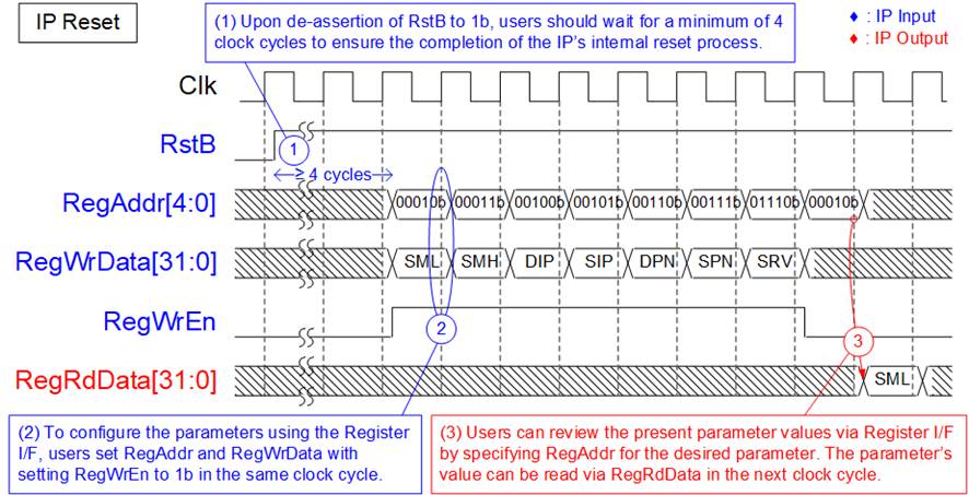
Figure 4: Register interface after the IP is reset
1) Following the transition of RstB from 0b to 1b, the IP remains inaccessible for write and read access on the Register I/F for 4 clock cycles.
2) After this period, users can initiate Register write to define values for the host and target parameters, including SML, SMH, DIP, SIP, DPN, SPN, and SRV registers. For Fixed-MAC mode, DML and DMH registers must also be assigned. These parameters must be valid before de-asserting RST register value to 0b, initiating the IP initialization process. Detailed descriptions of this process are outlined in subsequent section. The timing diagram for Register write is similar to that of Single-port RAM write access. Address and data setting must accompany the activation of RegWrEn to 1b to initiate write access to each register.
3) User can verify the set values or access other IP statuses via Register read access. The address for read access shared the signal used for write access, while data is retrieved on RegRdData with a one-clock latency period.
IP Initialization
The TOE10G IP begins the IP initialization process when the user updates RST register from 1b to 0b. Before de-asserting the RST register, the user must set the values of SML, SMH, DIP, SIP, DPN, SPN, and SRV registers. For Fixed MAC mode, the values of DML and DMH registers must also be set. These parameters must retain their values while the RST register remains at 0b, indicating that the IP is not reset. Upon successful completion of IP initialization, the �IP Busy� flag transitions from 1b to 0b.
The TOE10G IP offers three initialization modes, determined by the settings in the SRV register. Detailed information about each initialization mode is provided in this section.
Client mode (SRV[1:0]=00b)
When the target and the host are installed within the same network, the MAC address of the target can be obtained through ARP packet exchange. For simple usage, it is recommended to set the initialization mode of TOE10G IP to Client mode. The process of initialization in Client mode is described as follows.

Figure 5: IP Initialization in Client mode
1) Configure the target and host parameters of the TOE10G IP by assigning values to RegWrData while setting RegWrEn to 1b (as shown in Figure 4). Set the SRV register (RegAddr=01110b) to 0 for initialization in Client mode. After setting, these parameters are loaded to the internal registers.
2) Initiate the IP�s initialization process by updating the RST register value from 1b to 0b, setting RegAddr=00000b and RegWrEn=1b.
3) The parameters obtained in step 1) are used to construct an ARP request packet, which will be transmitted to the target.
4) Upon detecting an ARP request packet, the target generates an ARP reply packet to return its MAC address to the host.
5) Once the ARP reply packet has been received, the target�s MAC address is extracted and loaded into the internal registers. Following this, the �IP Busy� flag is set to 0b (monitored by bit[0] of RegDataA1 signal, or bit[0] of RegRdData when RegAddr=00001b or CMD register), signifying the completion of the IP initialization process. Additionally, the IP state (monitored by bits[3:1] of RegRdData when RegAddr=CMD register) changes from 101b (Initialization) to 001b (Idle).
Server mode (SRV[1:0]=01b)
Server mode is suitable for applications that employ both the TOE10G IPs as the host and the target. If the first device is initialized in Client mode, the subsequent device must be configured to Server mode. Figure 6 shows the timing diagram of IP initialization in Server mode.

Figure 6: IP Initialization in Server mode
The steps for Server initialization mostly align with those for Client initialization, with two distinctions. First, the SRV register is set to 1 to select Server mode. Second, the ARP packet transfer operates in reverse compared to Client mode. In Server mode, the IP awaits an ARP request packet to retrieve the target�s MAC address and then returns an ARP reply packet, completing the IP initialization process.
Fixed MAC mode (SRV[1]=1b)
The last initialization mode, known as Fixed MAC mode, is utilized when the host and the target are installed in different networks. In this mode, the MAC address of the target is configured by the gateway�s MAC address, assigned by DML and DMH registers. The initialization process in Fixed MAC mode is described in detail as follows.
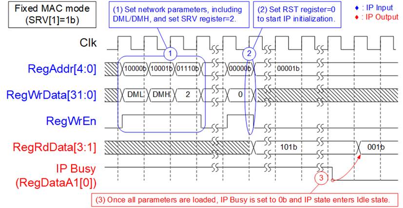
Figure 7: IP Initialization in Fixed MAC mode
1) Configure the target and host parameters of the TOE10G IP by assigning values to RegWrData while setting RegWrEn to 1b (as shown in Figure 4). DML and DMH are necessary to be configured in this step when aiming Fixed MAC initialization. After that, set the SRV register (RegAddr=01110b) to 2 for initialization in Fixed MAC mode. These parameters are loaded to the TOE10G IP internal registers.
2) Initiate the IP�s initialization process by updating the RST register value from 1b to 0b, setting RegAddr=00000b and RegWrEn=1b.
3) Once parameter loading has been completed, the �IP Busy� flag is set to 0b (monitored by bit[0] of RegDataA1 signal, or bit[0] of RegRdData when RegAddr=00001b or CMD register), signifying the completion of the IP initialization process. Additionally, the IP state (monitored by bits[3:1] of RegRdData when RegAddr=CMD register) changes from 101b (Initialization) to 001b (Idle).
Connection Establishment
After completing the IP initialization, the connection must be established for data transfer. The IP offers two options: active open and passive open. In active open, the IP initiates the connection establishment when users set CMD register=10b, commonly known as Client mode. Conversely, passive open involves the target initiating the connection establishment by sending a SYN packet, referred to Server mode. In passive open, the target defined its port number in the SYN packet, so the value of DPN register is unused. Users can also verify the target-defined port number by reading the DPN register after the connection has been established. Upon successful connection establishment, the ConnOn signal is set to 1b. Comprehensive information regarding the connection establishment is available in this section.
Active open or Client mode (CMD[1:0]=10b)
To initiate an active open connection, the target port number is defined by DPN register. Thus, the user must know the port number that the target can accept. For certain target systems, the user needs to execute the application, enabling it to listen on the specified port number before initiating the Client function. The procedure for executing the active open command is outlined as follows.
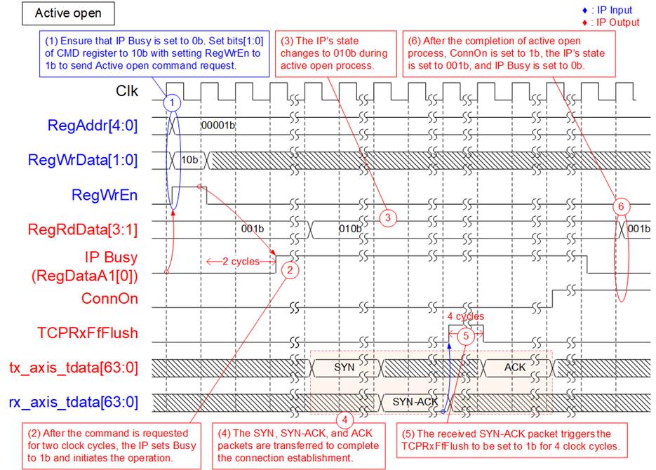
Figure 8: Active open operation
1) Verify that the IP is in an Idle state with no established connection, indicated by both the IP Busy flag and ConnOn set to 0b. After that, set bits[1:0] of CMD register (RegAddr=00001b) to 10b to initiate the active open operation.
2) The IP initiates operations and asserts the IP Busy to 1b. The IP Busy latency time following the setting of CMD register equals two clock cycles.
3) After that, the IP�s state, assessed via bits[3:1] of the CMD register, transitions from 001b (Idle) to 010b (Active open).
4) The network parameters, previously set by users during the IP initialization process, are utilized to construct a SYN packet sent to the target. If the target accepts the connection establishment request, it responds with a SYN-ACK packet. Subsequently, the IP generates an ACK packet to confirm the completion of the connection establishment.
5) Upon receiving the SYN-ACK packet from the target, the TCPRxFfFlush is set to 1b for 4 clock cycles, causing the Rx data buffer to clear all existing data.
6) Following this sequence, ConnOn switches to 1b, indicating the readiness of the connection for data transfer. Additionally, the IP transitions back to 001b (Idle) while setting IP Busy to 0b, signifying the completion of the operation.
Passive open or Server mode
Unlike active open, the TOE10G IP offers an alternative method for connection establishment known as passive mode. In passive mode, the sequence of packet transfer is reversed compared to active mode. In this mode, the target port number is extracted from the SYN packet, not configured by the user. The procedure for the passive open command is outlined as follows.
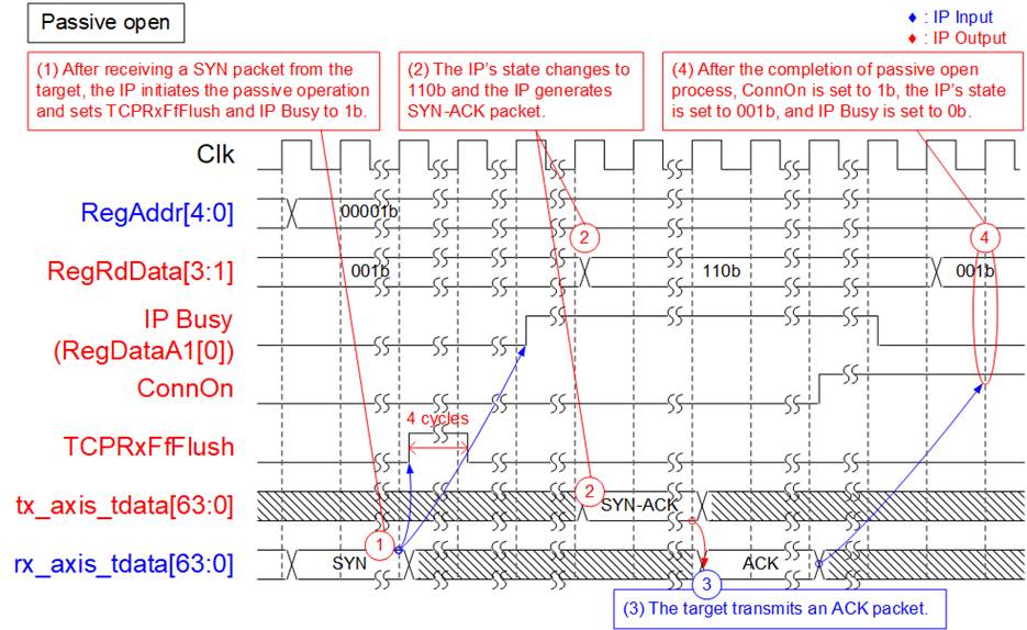
Figure 9: Passive open operation
1) Passive open is initiated upon reception of a SYN packet containing the correct parameters in the packet header from the target. Concurrently, the IP must be in an Idle state with no established connection, indicated by both the IP Busy flag and ConnOn set to 0b. Upon acceptance of the connection establishment request, the IP triggers operations and asserts both the IP Busy and TCPRxFfFlush to 1b. The TCPRxFfFlush is set to 1b for 4 clock cycles, causing the Rx data buffer to clear all existing data.
2) Following this, the IP�s state, assessed via bits[3:1] of the CMD register, transitions from 001b (Idle) to 110b (Passive open). Additionally, the SYN-ACK packet, constructed using network parameters set by users, serves as a response to the connection establishment request.
3) Subsequently, the target generates an ACK packet to confirm the completion of the connection establishment.
4) Upon this sequence, ConnOn switches to 1b, indicating the readiness of the connection for data transfer. Additionally, the IP transitions back to 001b (Idle) while setting IP Busy to 0b, signifying the completion of the operation.
Flush operation of the Rx data buffer during connection establishment
When the connection establishment for both active and passive modes is operated, the Rx data buffer undergoes a flush operation. All data in the buffer is cleared.
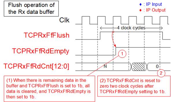
Figure 10: Flush operation of the Rx data buffer during the connection establishment
1) If there is any remaining data in the Rx data buffer and TCPRxFfFlush has been set to 1b during the connection establishment process, all data within the buffer is cleared. This action results in TCPRxFfRdEmpty being set to 1b in the next clock cycle.
2) The TCPRxFfRdCnt, which indicates the amount of data in the Rx data buffer, is reset to zero after TCPRxFfRdEmpty is set to 1b, with a latency of two clock cycles. During the transition from the previous value to zero, the TCPRxFfRdCnt value is temporarily incorrect for a single clock cycle.
Connection Termination
Terminating a connection can be initiated by either the TOE10G IP (active close) or the target (passive close). An active close occurs when users set the CMD register to 11b. Conversely, passive close occurs when the target sends a FIN packet. If the target sends a FIN packet while the IP is executing the �Send data� command, the IP halts the �Send data� command and accepts the connection termination request from the target. During processing the connection termination, the Tx data buffer flushes all remaining data. Upon successful connection termination, the ConnOn signal is set to 0b. Additional information about connection termination is provided in this section.
Active close (CMD[1:0]=11b)
Before sending an active close command, ensure that the ConnOn is set to 1b and IP Busy is set to 0b. The procedure for the active close command is outlined as follows.
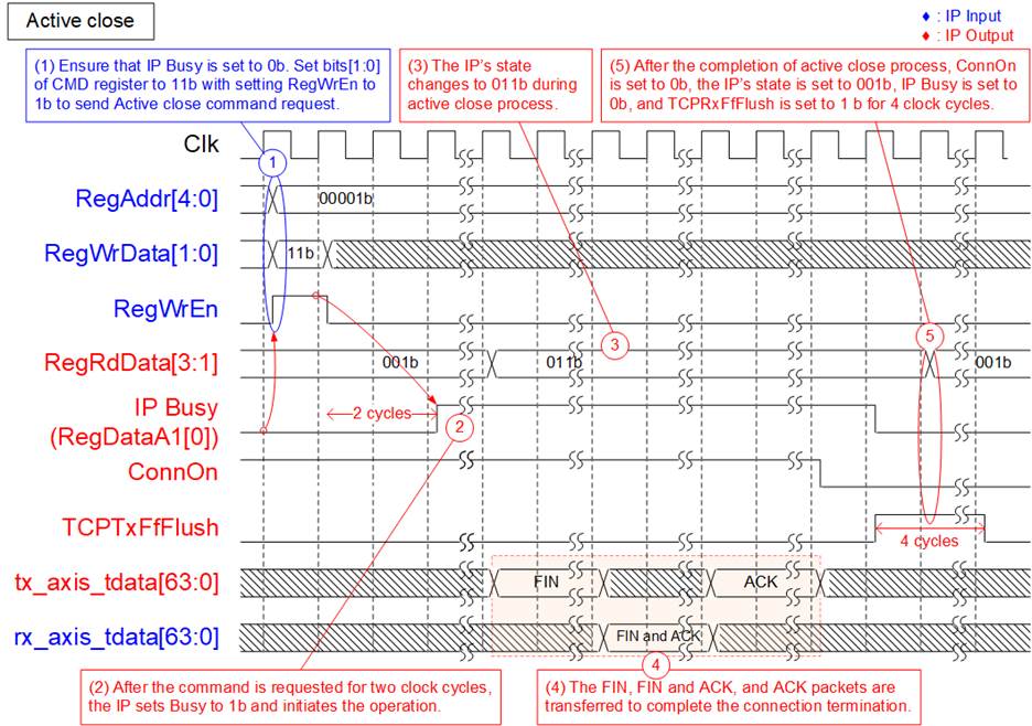
Figure 11: Active close operation
2) The IP initiates operations and asserts the IP Busy to 1b. The IP Busy latency time following the setting of CMD register equals two clock cycles.
3) After that, the IP�s state (bits[3:1] of the CMD register) transitions from 001b (Idle) to 011b (Active close).
4) The IP constructs a FIN packet sent to the target. If the target accepts the connection termination request, it responds with FIN and ACK packets. Subsequently, the IP generates an ACK packet to confirm the completion of the connection termination.
5) Once the ACK packet is transmitted, the IP updates several signals to show the current status.
· ConnOn switches to 0b, indicating an inactive connection.
· IP Busy flag transitions to, signifying command completion.
· TCPTxFfFlush is set to 1b for 4 clock cycles, clearing data in the Tx data buffer.
· The IP�s state transitions from 011b (Active close) to 001b (Idle).
Passive close
In passive close, the connection termination is initiated by the target. This results in a reversal of the packet transfer sequence compared to an active close. The procedure for the passive close command is outlined as follows.
Figure 12: Passive close operation
1) Passive close is initiated upon reception of a FIN packet containing the correct parameters in the packet header from the target. Concurrently, the IP must be in an Idle state with an active connection, indicated by the IP Busy flag set to 0b and ConnOn set to 1b. Upon acceptance of the connection termination request, the IP triggers operations and asserts the IP Busy to 1b.
2) Following this, the IP�s state transitions from 001b (Idle) to 111b (Passive close). Additionally, it constructs FIN and ACK packets in response to the termination request.
3) Subsequently, the target generates an ACK packet to confirm the completion of the connection termination.
4) Following this sequence, ConnOn switches to 0b, indicating an inactive connection. Then TCPTxFfFlush is set to 1b for 4 clock cycles, clearing data in the Tx data buffer.
5) After a specific latency period, the IP transitions back to 001b (Idle) while setting IP Busy to 0b, signifying the completion of the operation.
Passive close during executing Send data command
While the Send data command is being executed, if the target sends a FIN packet to terminate the connection, the IP will immediately halt data transmission and switch into connection termination mode. Any remaining data in the Tx data buffer will be flushed upon the completion of the connection termination process. The steps for handling passive close under this condition are outlined below.
Figure 13: Passive close during executing Send data command
1) While the IP executes the �Send data� command and the IP�s state equals 000b (Send data), if the target sends a FIN packet to stop data transmission and terminate the connection, the IP will pause the �Send data� process. It will then switch to execute the termination request, setting the IP�s state to 111b.
2) The IP creates FIN and ACK packets to acknowledge the termination request.
3) Following this, the procedure for terminating the connection in passive mode is similar to steps 3) � 5) in Figure 12. Once the connection is terminated, the user can read the TDL register to check the amount of data requested by user that has not been transmitted.
Flush operation of the Tx data buffer during connection termination
After the connection has been terminated for both active and passive mode, the Tx data buffer undergoes a flush operation. This operation clears all data stored in the buffer and the TCPTxFfFlush is set to 1b for 4 clock cycles.

Figure 14: Flush operation of the Tx data buffer during the connection termination
If any data remains in the Tx data buffer when TCPTxFfFlush is asserted to 1b during the connection termination process, all the data within the buffer is cleared. After that, TCPTxFfFull is set to 1b, and TCPTxFfWrCnt is reset to zero in the next clock cycle.
Data Transmission
Data transfer can commence when the connection is still active. Users send data to the IP via the 64-bit TxFIFO interface. Parameters related to data transmission, including the TDL, PKL, and PSH registers, are configured using the Register interface. These registers are utilized for setting the total transmitted size (TDL), the TCP payload size per Tx packet (PKL), and the transmission mode (PSH). Once all parameters are set, users initiate data transmission by setting the CMD register. Additionally, while executing the �Send data� command, users can expand the total transmitted size by setting ETL register.
According to TCP/IP specification, the maximum payload size in each Ethernet packet is constrained by the Maximum Segment Size (MSS). Consequently, to optimize transmission performance, the set value of PKL register should match the MSS value with 64-bit alignment. If the TDL value exceeds the PKL value, multiple packets are transmitted to the target.
Typically, the target generates an ACK packet to confirm data reception once the received data reaches the predefined threshold value. When the last data is transmitted without a special flag, the target awaits additional data until a timeout triggers the generation of the ACK packet. Excessive waiting time in relation to processing time can potentially affect the system�s transfer performance. To mitigate waiting time, the TOE10G IP offers two additional features, configured by bits[1:0] of PSH register, to expedite the ACK packet.
The first mode, set by bit[0], involves duplicating the last data packet when the TDL value does not align with the PKL value. The target recognizes the second data packet as a data retransmission, which accelerates the target�s response in generating an ACK packet. In our test environment, this mode resulted in a shorter response time for the ACK packet compared to the second mode.
The second mode, set by bit[1], involves the PSH flag value of the packet header within each transmitted packet. According to TCP/IP standard, the target must bypass data to the application layer if PSH flag is found. Therefore, this allows the target to respond with an ACK packet without prolonged waiting.
Besides, the IP allocates bit[2] of the PSH register to enable data retransmission. This feature initiates a retransmission process when the target exhibits an insufficient window size, causing a pause in data transmission until the timeout duration is reached.
Further details on transmitting data under various conditions can be found in this section.
Data transmission using Tx FIFO interface
Transmitted data from user is sent via Tx FIFO interface, which provides two flow control signals, the full flag (TCPTxFfFull) and the write data counter (TCPTxFfWrCnt). TCPTxFfWrCnt is updated after asserting TCPTxFfWrEn for two clock cycles, allowing the user logic to write data in burst transfer. TCPTxFfFull serves as an indicator of when the Tx data buffer is almost full and is asserted before it reaches its capacity. It is recommended to pause sending data within four clock cycles after TCPTxFfFull is asserted. Further details of the Tx FIFO interface are shown in Figure 15.
Figure 15: Data transfer using Tx FIFO interface
1) Before setting TCPTxFfWrEn to 1b, ensure that the connection is active, indicated by ConnOn set to 1b, and the FIFO does not reach its capacity, indicated by TCPTxFfFull set to 0b. Once both conditions are met, users can send data to the Tx data buffer by setting TCPTxFfWrEn to 1b, transferring the 64-bit data via the TCPTxFfWrData signal.
2) Under specific conditions where user logic demands continuous transfer in burst mode, the FIFO data counter (TCPTxFfWrCnt) must be used to verify that sufficient space remains for the next data burst transfer. Please note that there is a latency time of two clock cycles for updating TCPTxFfWrCnt after the assertion of TCPTxFfWrEn. Therefore, the current read value may be two less than the actual TCPTxFfWrCnt value.
3) When the Tx data buffer almost reaches its capacity, TCPTxFfFull is asserted to 1b. As a result, TCPTxFfWrEn must be de-asserted to 0b within four clock cycles to pause sending data before the buffer overflow.
4) The data transmission can be resumed after TCPTxFfFull changes back to 0b.
Data transmission when TDL value aligns to PKL value
Figure 16 illustrates the data transmission scenario when users set the TDL value to align with the PKL value, following the equation: TDL = n x PKL, where �n� represents an integer value indicating the number of packets. In this example, �n� equals two. Once the user data stored in the Tx data buffer is enough, indicated by TCPTxFfWrCnt, a packet is created and transmitted to the target. The operation is completed once the target returns ACK packets to confirm the successful reception of all transmitted data. The sequential steps for transmitting data under this condition are outlined below.
Figure 16: Data transmission when TDL value aligns to PKL value
1) Ensure that the ConnOn is set to 1b, and the IP Busy flag is set to 0b. Then, users configure the total transmitted size in the TDL register (RegAddr=01000b) and the transmitted packet size in the PKL register (RegAddr=01010b). Assumes that PKL = N and TDL = 2N.
2) Users proceeds to set the CMD register (RegAddr=00001b) to �Send data� (RegWrData[1:0]= 00b), initiating the data transmission operation and the assertion of the IP Busy flag. After that, the IP�s state, decoded by bits[3:1] of RegRdData when RegAddr=00001b, is set to 000b (Send data).
3) The IP monitors the amount of data stored in the Tx data buffer. When at least N-byte data (�N� represents the PKL value) is stored in the Tx data buffer, an Ethernet packet including N-byte data is generated and transmitted to the target. This process iterates until the total transmitted data, configured by the TDL value or 2N in this scenario, is transmitted to the target. However, the transmit process may be paused if the received buffer space is insufficient.
4) Upon receiving an ACK packet from the target, confirming the reception of all data, the IP Busy flag switches to 0b, signifying the completion of the operation. If users send 2N-byte data to the Tx data buffer, the �TCPTxFfWrCnt� becomes zero upon the completion of the operation.
5) Without any error, the IP�s state returns to 001b (Idle), and the read value of TDL (RegAddr=01000b) becomes zero.
Data transmission with enabling last packet retransmission (bit[0] of PSH register=0b)
When the total transmitted size does not align with the PKL value and the last packet retransmission mode (set by configuring bit[0] of the PSH register to 0b) is activated, the IP duplicates the last packet to accelerate an ACK packet response from the target. Before sending the last packet, all transmitted packets contain the same payload size, defined by the PKL value. The IP waits for an ACK packet from the target to confirm successful reception of all data aligned to the PKL value before adjusting the packet size for transmitting the last packet.
Figure 17 illustrates the process of last packet retransmission when the TDL does not align with the PKL value. Assuming TDL = 2N + M, where �N represents the PKL value and M is less than N. The sequential steps for transmitting data under this condition are outlined below.
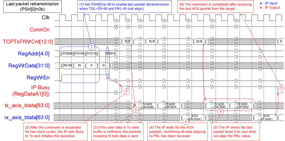
Figure 17: Data transmission with enabling last packet retransmission
1) Users configure the TDL register (RegAddr=01000b) for the total transmission size, the PKL register (RegAddr=01010b) for the packet size, and set bit[0] of the PSH register (RegAddr= 01011b) to 0b to enable last packet retransmission. However, the TDL value does not align with the PKL value.
2) Users proceeds to set the CMD register (RegAddr=00001b) to �Send data� (RegWrData[1:0] =00b), initiating data transmission operation and asserting the IP Busy flag.
3) The IP monitors the amount of data stored in the Tx data buffer. When at least N-byte data (�N� represents the PKL value) is stored in the Tx data buffer, an Ethernet packet including N-byte data is generated and transmitted to the target. This process iterates until the total transmitted data that aligns with the PKL value is transmitted to the target. In this case, the alignment size is 2N. However, the transmission process may be paused if the received buffer space is insufficient.
4) The IP waits for an ACK packet from the target, confirming the reception of all aligned data.
5) Upon having sufficient data in the Tx data buffer, the IP sends the last packet, which includes the remaining M-byte twice, as specified by bit[0] of the PSH register.
6) Once the last ACK packet is received, the operation is completed and the IP Busy flag is de-asserted to 0b. If users send (2N+M)-byte data to the Tx data buffer, the �TCPTxFfWrCnt� becomes zero upon the completion of the operation.
Data transmission with PSH flag assertion (bit[1] of PSH register=1b)
The PSH flag inside each transmitted packet is determined by bit[1] of the PSH register. When users set this bit to 1b, the PSH flag within the TCP header is activated, allowing the target to bypass data to the application layer in compliance with the TCP/IP standard. Figure 18 illustrates an example of transmitting packets with the PSH flag asserted.
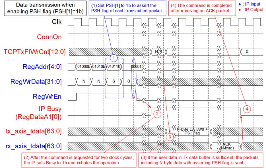
Figure 18: Data transmission with PSH flag assertion
1) Users set bit[1] of the PSH register (RegAddr=01011b) to 1b, causing the PSH flag in the TCP header to be asserted for every transmitted packet.
2) Users proceeds to set the CMD register (RegAddr=00001b) to �Send data� (RegWrData[1:0]= 00b), initiating data transmission operation and asserting the IP Busy flag.
3) The IP monitors the amount of data stored in the Tx data buffer. When at least N-byte data (�N� represents the PKL value) is stored in the Tx data buffer, an Ethernet packet containing N-byte data with the PSH flag asserted is generated and transmitted to the target. In this case, users request the transmission of a single packet.
4) Upon receiving the ACK packet, the operation is completed and the IP Busy flag is de-asserted to 0b.
Data transmission with timeout triggered by insufficient window size (bit[2] of PSH register=1b)
Configuring bit[2] of the PSH register enables a timeout function when the latest received packet from the target indicates insufficient space for storing the next packet in receive buffer. This pauses packet transmission until the target frees up space. However, if the target does not return an ACK packet with an updated window size (through a TCP Window update packet), or the TCP Window update packet itself is lost, the packet transmission remains stalled indefinitely.
To resolve this issue, a timeout mechanism is designed. If no ACK packet arrives within the timeout period, the IP generates a small retransmission packet containing 8-byte data to prompt a response for an ACK packet. Receiving an ACK packet with sufficient window size resumes packet transmission. Figure 19 provides a detailed example showcasing data transmission under these specific conditions.
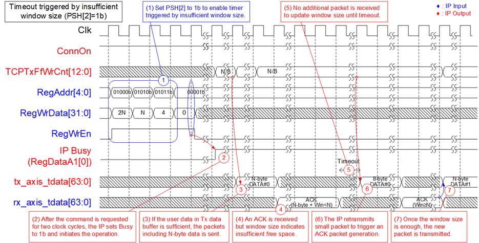
Figure 19: Data transmission when timeout triggered by insufficient window size
1) Ensure that the ConnOn is set to 1b, and the IP Busy flag is set to 0b. Then, users configure the total transmitted size in the TDL register (RegAddr=01000b) and the transmitted packet size in the PKL register (RegAddr=01010b). Assumes that PKL = N and TDL = 2N.
2) Users proceeds to set the CMD register (RegAddr=00001b) to �Send data� (RegWrData[1:0]= 00b), initiating the data transmission operation and the assertion of the IP Busy flag.
3) The IP monitors the amount of data stored in the Tx data buffer. When at least N-byte data (where �N� represents the PKL value) is stored in the Tx data buffer, an Ethernet packet including N-byte data is generated and transmitted to the target. If the received buffer space is insufficient, data transmission pauses.
4) Upon receiving an ACK packet confirming the reception of N-byte data but encountering inadequate space in the received buffer space, the IP remains paused, awaiting sufficient buffer space. A timer starts to measure the waiting time.
5) If no additional ACK packet is received within the timeout period, packet retransmission is initiated.
6) The IP generates a retransmission packet with an 8-byte payload data to prompt the target to send an updated ACK packet.
7) Upon receiving a TCP Window update packet from the target, indicating adequate space in the received buffer, packet transmission resumes.
Data transmission with extending transmission length by setting ETL register
When using the TDL register to set transmission length, the maximum size is limited to 4 GB. In cases where users need to transmit data exceeding this limit without using the ETL register, they must wait for the completion of the first �Send data� command before issuing subsequent �Send data� commands. This waiting period affects transfer performance, especially in applications sensitive to timing.
To address this issue, the ETL register is specifically designed to extend the transmission length of the ongoing �Send data� command without waiting for its completion. The maximum value of TDL value is 4 GB, so it is crucial to ensure that the IP continues executing the �Send data� command with the result of TDL register remains within this 4 GB limit, as outlined in the ETL register description. Figure 20 illustrates an example result following the configuration of the ETL register during the execution of the �Send data� command.
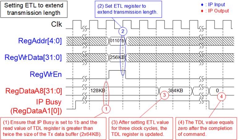
Figure 20: The result of TDL register after setting ETL register
1) Confirm the continued operation of the �Send data� command by checking the IP Busy set to 1b and verifying that the TDL register value (RegDataA8) exceeds twice the size of the Tx data buffer. Assuming a Tx data buffer size of 64 KB, a size of 128 KB size is adequate.
2) Configure the additional transmission length into the ETL register by setting RegAddr to 01101b, setting RegWrData to the additional transmission length, and enabling RegWrEn to 1b. Ensure that the combined value of the TDL value from step 1) and the newly set ETL value (in this example, ETL value equals 256 KB) remains below 4 GB to prevent an overflow in the TDL register.
3) After waiting for three clock cycles, the TDL value is updated to the new value (128KB + 256KB = 384 KB).
4) If all data is successfully transmitted, the TDL value after command completion will be zero. However, if the ETL is set too late and the �Send data� command completes before loading the additional transmission length from ETL, the TDL register after command completion will not be zero but will match the ETL value, indicating the amount of requested but unsent data.
Data Reception
When the TOE10G IP receives data from the target, it checks the packet sequence and verifies if the amount of received data reaches threshold value. Upon meeting these criteria, an ACK packet is generated to confirm the acceptance of the data. Simultaneously, the received TCP payload data is stored in the Rx data buffer, accessible to users via the Rx FIFO interface. TCPRxFfRdEmpty and TCPRxFfRdCnt signals are provided to allow users to track the available data within this buffer.
During the ACK packet generation process, the TOE10G IP transitions its state from �Idle� to �Receive data�, and the IP Busy flag is set to 1b.
The ACK packet returned to the target includes the �Window size� value, indicating the free space available within the Rx data buffer. The value helps the target determine the maximum data size it can transmit to the TOE10G IP without awaiting an ACK packet. If users do not read data from the Rx data buffer within a specified time, reaching its capacity, the �Window size� reduces to zero, signaling the target to halt data transmission.
At this point, the TOE10G IP checks the �WIN� register to compute a threshold value for additional free space in the Rx data buffer, prompted by users accessing data. When this extra space meets the threshold, the IP generates a TCP Window update packet (an updated ACK packet, which includes the new �Window size� value). Subsequently, the target can resume transmitting data, aligned with this updated Window size.
Further details on receiving data under different conditions can be found in this section.
Data transfer using Empty flag of Rx FIFO interface
The Rx FIFO interface is used to retrieve data stored in the Rx data buffer. The Empty flag (TCPRxFfEmpty) serves as an indicator of data availability. Users can use this flag to trigger the read enable signal, allowing them to retrieve data, similar to a standard FIFO read interface, as illustrated in Figure 21.
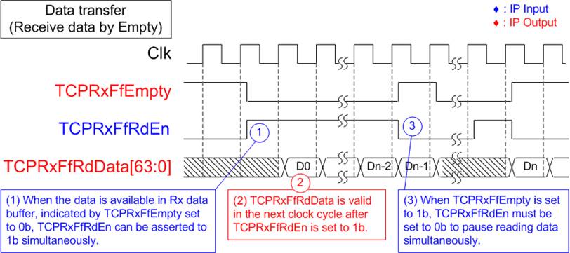
Figure 21: Data transfer using Empty flag of Rx FIFO interface
1) Check the TCPRxFfEmpty flag to confirm data availability. When data is ready (TCPRxFfEmpty=0b), set TCPRxFfRdEn to 1b to read data from the Rx data buffer.
2) The TCPRxFfRdData signal is valid in the next clock cycle.
3) Reading data must be immediately paused by setting TCPRxFfRdEn=0b when TCPRxFfEmpty is equal to 1b.
Data transfer using Read count of Rx FIFO interface
The TOE10G IP offers the TCPRxFfRdCnt signal, indicating the total amount of data stored in the Rx data buffer in 64-bit units. In cases where received data does not align with a 64-bit unit, the remaining bytes stored in the Rx data buffer, yet to be read, are indicated by the TCPRxFfLastRdCnt signal. Leveraging the Read count signal, users can activate TCPRxFfRdEn to retrieve multiple data from the Rx data buffer, as illustrated in Figure 22.
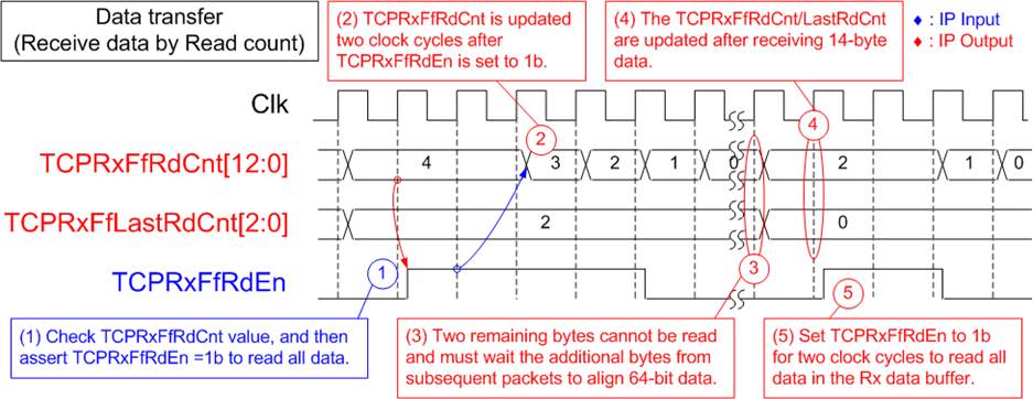
Figure 22: Data transfer using Read count of Rx FIFO interface
1) To verify the amount of received data, observe the TCPRxFfRdCnt signal. For instance, if four 64-bit data are stored, user can assert TCPRxFfRdEn for four clock cycles to read all available 64-bit data.
2) After setting TCPRxFfRdEn to 1b, TCPRxFfRdCnt updates its value two clock cycles later. Therefore, upon de-asserting TCPRxFfRdEn, wait for two clock cycles to confirm the accurate TCPRxFfRdCnt value before initiating the next read transfer.
3) In this scenario, two bytes of data remain in the Rx data buffer, indicated by TCPRxFfLastRdCnt. This data cannot be read and must await new data to align with 64-bit data units.
4) Let�s assume the target transmits a subsequent packet containing 14 bytes of data. Currently, the Rx data buffer holds a total of two 64-bit data, as indicated by TCPRxFfRdCnt=2.
5) Users assert TCPRxFfRdEn for two clock cycles to read all remaining data. Upon completing the data transfer, both TCPRxFfRdCnt and TCPRxFfLastRdCnt will be zero.
Data reception after receiving 8960 bytes of data
Figure 23 illustrates the data reception scenario when the target sends a packet containing 8960 bytes of data while the TOE10G IP is in Idle and the Rx data buffer has no remaining data. Once the packet is validated, its payload data is stored in the Rx data buffer for user access. Simultaneously, the IP generates an ACK packet to confirm the successful reception of data. The sequential steps for receiving data under this condition are outlined below.
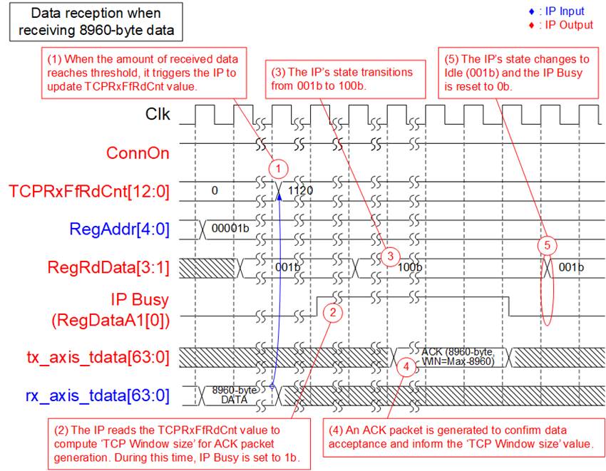
Figure 23: Data reception after receiving 8960-byte data
1) When the connection is active (ConnOn=1b), the target transmits a packet containing 8960 bytes of data. If the IP is in an Idle state, this data size triggers the IP to process the packet. After successful verification, the data becomes accessible to users, updating the �TCPRxFfRdCnt� value from 0 to 1120 (1120 x 64-bit = 8960 bytes).
2) The TOE10G IP starts the process of generating an ACK packet. During this phase, the IP Busy flag is set to 1b. The IP reads the �TCPRxFfRdCnt� value to calculate the available space in the Rx data buffer. This calculated result becomes the �TCP Window size� value in the ACK packet sent back to the target.
3) The IP�s state, identified by bits[3:1] of RegRdData when RegAddr=00001b, transitions from 001b (Idle) to 100b (Receive data).
4) An ACK packet is generated to confirm the receipt of all 8960 bytes of data. Additionally, the �TCP Window size� is adjusted to (the maximum value � 8960) if users have not read any data from the Rx data buffer.
5) Upon completion of the ACK packet generation, the IP Busy flag resets to 0b, and the IP�s state reverts to 001b (Idle).
TCP Window update packet generation during data reception
When users temporarily pause reading data from the Rx data buffer until it reaches capacity, the target must halt data transmission to the TOE10G IP. To facilitate this, configuring the �WIN� register becomes crucial, allowing the generation of a �TCP Window update� packet when the additional space within the Rx data buffer meets the specified threshold. Upon receipt of the TCP Window update packet, indicating the available additional space, the target can resume transmitting data to the TOE10G IP. Further details on this functionality are outlined in Figure 24.
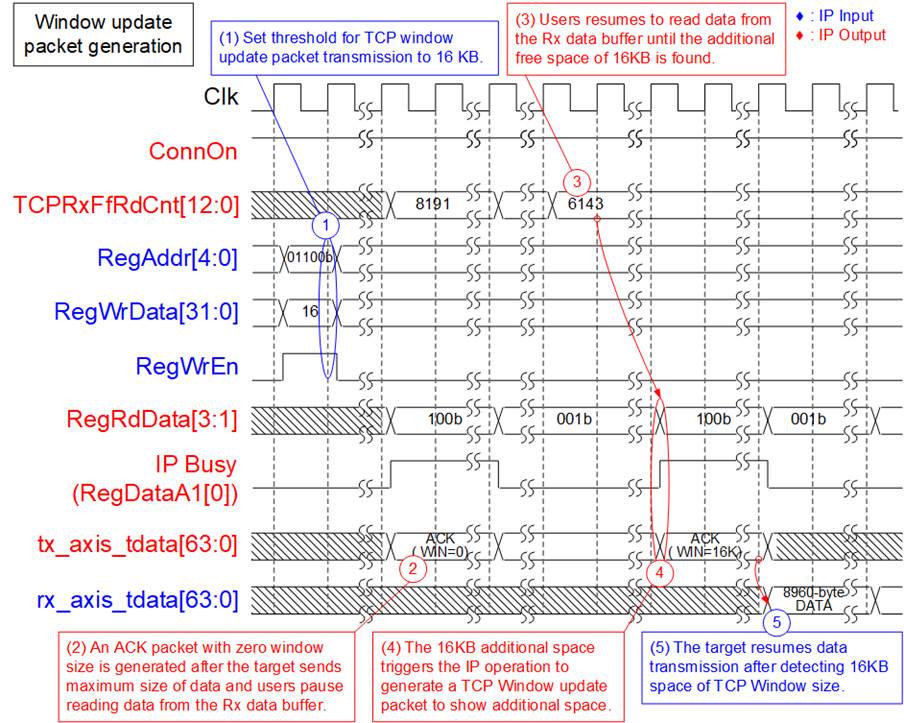
Figure 24: TCP Window update packet generation during data reception
1) Set the threshold value for triggering the generation of the �TCP Window update� by writing to RegAddr as 01100b (WIN register), setting RegWrData to the desired threshold value in KB units, and setting RegWrEn to 1b. For instance, configuring RegWrData to 16 sets the Window threshold to 16 KB.
2) Let�s assume users temporarily pause reading data while the target continues transmitting until the Rx data buffer reaches full capacity, indicated by TCPRxFfRdCnt=8191. At this point, the last ACK packet sent from the TOE10G IP displays a �TCP Window size� of zero.
3) Upon users resuming data reading, TCPRxFfRdCnt decreases accordingly. If 16KB of data is read, TCPRxFfRdCnt changes from 8191 to 6143 (indicating 2048 x 64-bit free).
4) As the additional free space matches the threshold set for the �TCP Window size�, the IP triggers the initiation of the �TCP Window update� packet generation. This results in the �TCP Window size� increasing from 0 to 16K.
5) Upon detecting the available space in the TOE10G IP receive buffer, the target resumes data transmission by sending the subsequent packet, inclusive of payload data.
Timeout Interrupt
The TOE10G IP includes a timer designed to track the wait duration for a received packet from the target. If the expected packet is not received within the set timeout value, the IP triggers either packet retransmission to recover the lost packet or a RST/FIN packet transmission. Additionally, the �TimerInt� signal is asserted to 1b for a single clock cycle, notifying users of this event. Users can monitor the timeout interrupt status by either reading the TMO register or the RegDataA9 signal.
Generally, the retry process sets a maximum limit of 16 attempts to recover the lost packet. If the lost packet remains unresolved, the TOE10G IP executes a final action by transmitting either �RST� or �FIN� packet to conclude the operation. For a comprehensive understanding of the interrupt signals, please refer the detailed information provided in this section.
Timeout Interrupt: Lost ARP reply packet (TMO[0])
The timeout interrupt related to lost ARP reply packets is identified as bit[0] within the TMO register or RegDataA9 signal. This process operates without a predefined maximum limit for retry attempts. The following steps present an example outlining the process of packet transmission to handle the recovery of lost ARP reply packets.
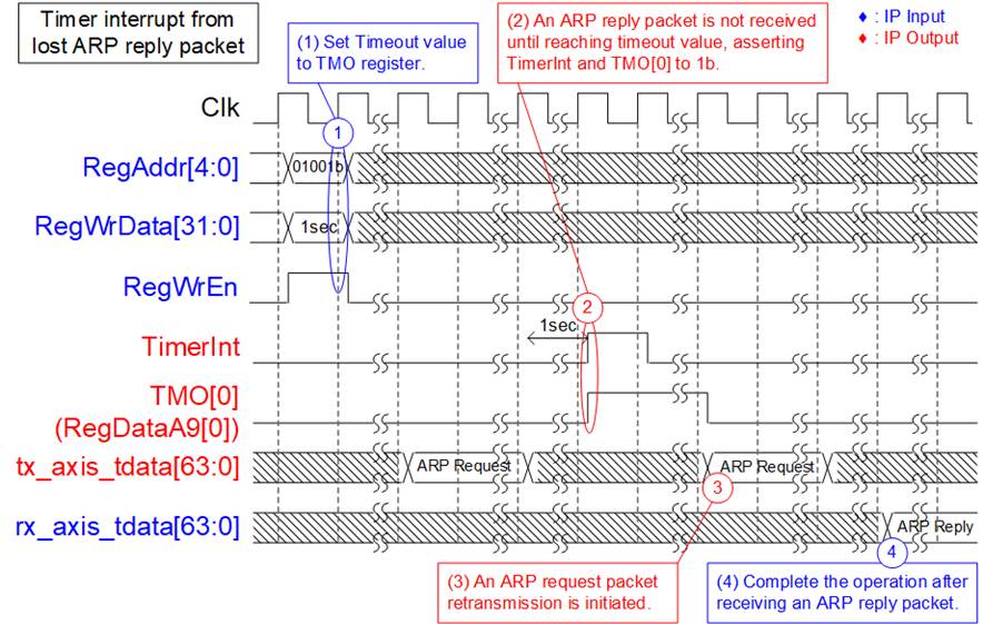
Figure 25: TMO[0] assertion
1) Users initialize the timeout value in the TMO register by writing to RegAddr as 01001b and asserting RegWrEn to 1b. The time unit specified in RegWrData is determined based on the �Clk� signal frequency.
2) In this scenario, assuming the IP is initialized in Client mode, where it transmits an ARP request packet and awaits the return of an ARP reply packet from the target. If the expected ARP reply packet is lost and does not arrive within the defined timeout value from step 1), the TimerInt triggers, and bit[0] of the TMO register or RegDataA9 signal is set to 1b.
3) The retry process begins by retransmitting the ARP request packet. With no predefined maximum retry count limit for this interrupt type, steps 2) and 3) repeat until the lost packet is successfully received.
4) Upon receiving the awaited ARP reply packet, the retry process concludes, marking the successful completion of the IP initialization process.
Timeout Interrupt: Lost SYN-ACK packet (TMO[1])
Typically, the retry process is limited to a maximum of 16 attempts before switching to the transmission of a �FIN� or �RST� packet. This limitation applies to five specific interrupt types denoted as bit[1], bit[2], bit[4], bit[5], and bit[7] within the TMO register or RegDataA9 signal. These interrupt statuses correspond to various conditions: lost SYN-ACK packet, lost ACK packet during passive open operation, lost ACK packet during passive close operation, lost ACK packet during data transmission, and lost TCP window update packet during data transmission.
This section provides an example illustrating the scenario of a lost SYN-ACK packet during the establishment of a connection in active mode. The subsequent steps during the execution of the retry process, which occurs multiple times, are outlined below.
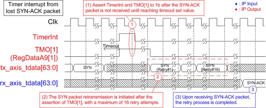
Figure 26: TMO[1] assertion
1) Consider a scenario where the IP initiates an active open command by sending a SYN packet to the target. If the SYN-ACK packet is not returned within the specified timeout period, both TimerInt and bit[1] of the TMO register/RegDataA9 signal are asserted to 1b.
2) Subsequently, the retry process commences by retransmitting the SYN packet after the assertion of TimerInt and TMO[1] register/RegDataA9[1] signal. This retransmission can continue for up to 16 attempts if the SYN-ACK packet is still not received.
3) Upon successfully receiving the SYN-ACK packet within 16 retry attempts, the connection establishment process is successfully completed.
As previously mentioned, the retry process is suspended after the 16th retransmission without successfully receiving the lost packet. To continue from the previous section, an example of the FIN packet transmission after the 16th attempt, without the reception of the SYN-ACK packet, is provided with further details below.
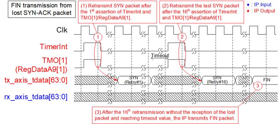
Figure 27: A FIN packet transmission upon the failure of the 16th attempt
1) After TimerInt and TMO[1] register/RegDataA9[1] signal are asserted, the first retransmission of the SYN packet is initiated.
2) In the absence of receiving the SYN-ACK packet, the process outlined in step 1) repeats for a total of 16 iterations. The transmission of the SYN (Retry#16) packet occurs during the final attempt.
3) Upon reaching the timeout threshold, it initiates the transmission of the FIN packet to the target.
Timeout Interrupt: Lost FIN-ACK packet (TMO[3])
Under the condition of bit[3] within the TMO register/RegDataA9 signal, signifying the loss of FIN and ACK packets during the termination of a connection in active mode, the RST packet is immediately transmitted to the target without any retry attempt after the timeout interrupt occurs. The subsequent steps, outlining the transmission of RST packet following the detection of lost FIN and ACK packets, are detailed below.
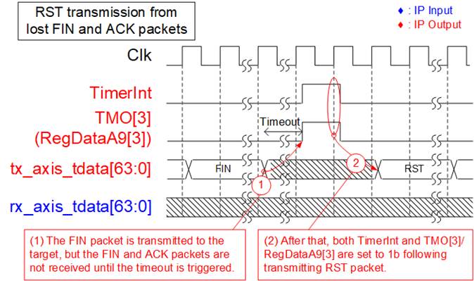
Figure 28: TMO[3] assertion
1) Upon the user initiating an active close command, a FIN packet is transmitted to the target. However, the target does not transmit FIN and ACK packets within the specified timeout duration.
2) Once the timeout duration is reached, triggering TimerInt and setting TMO[3] register/ RegDataA9[3] signal to 1b, the interrupt activates. Subsequently, the RST packet is dispatched to the target, initiating the termination of the connection without any further retries.
Ethernet MAC Interface
This AXI4-ST characteristic necessitates the implementation of special logic with small FIFO (TenGMacIF in Figure 2) on the transmission side between TOE10G IP and AMD Xilinx 10G/25G Ethernet Subsystem. On the contrary, the Ethernet MAC IP core from Design Gateway (DG 10G25GEMAC) is specially designed to address this interface, seamless connecting with TOE10G IP without additional logic.
Tx EMAC interface
During packet transmission, the tx_axis_tready signal needs to be consistently asserted to 1b from the transmission of the first data until the transmission of the last data within each packet. Only when the interface is in an Idle state before starting the transmission of the subsequent packet, tx_axis_tready can be de-asserted to 0b.
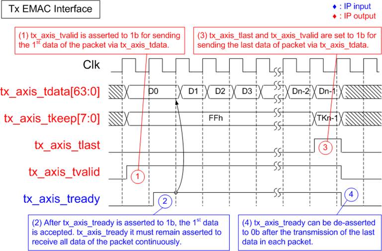
Figure 29: Tx EMAC Interface timing diagram
1) The TOE10G IP asserts tx_axis_tvalid to 1b when initiating transmission of the first packet data through the tx_axis_tdata signal. These signals maintain their value until the confirmation of data acceptance by asserting tx_axis_tready to 1b.
2) Once the first data is acknowledged, tx_axis_tready must remain set to 1b to receive all subsequent packet data from the TOE10G IP until the completion of the packet transmission. This ensures a continuous transfer of all data within each packet.
3) While transmitting the last data of the packet through tx_axis_tdata, both tx_axis_tlast and tx_axis_tvalid are asserted to 1b.
4) Upon completion of the transfer of the last packet data, tx_axis_tready can be set to 0b, enabling the pause of transmission for the next packet.
Rx EMAC interface
The Receive EMAC interface also requires continuous receipt of packet data, similar to Transmit EMAC interface. The rx_axis_tvaid signal must remain asserted at 1b from the start of the packet to the end of the packet without interruption, as shown in Figure 30.
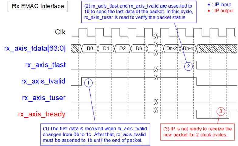
Figure 30: Rx EMAC Interface timing diagram without a pause for last data transfer
1) The TOE10G IP detects the start of the received frame when rx_axis_tvalid changes from 0b to 1b. In this cycle, the first data is valid on rx_axis_tdata. Afterward, rx_axis_tready is asserted to 1b to accept all data of this packet until the end of the packet. To continuously send the data of each packet, rx_axis_tvalid must remain set to 1b.
2) The end of the packet is detected when rx_axis_tlast=1b and rx_axis_tvalid=1b. In this cycle, the last data of the packet is valid on rx_axis_tdata, and the rx_axis_tuser is monitored to check the packet status.
3) After the final data of the packet has been transferred, the TOE10G IP de-asserts rx_axis_tready for 2 clock cycles to complete the packet post-processing. Therefore, the interface module must support pausing data packet transmission for 2 clock cycles.
Note: Typically, Ethernet MAC has a minimum idle state of two clock cycles between each received packet. This interval allows for the reception of Ethernet FCS, EFD, and IFG.
PKL and TDL setting in Send command
When the �Send data� command is executed, the TOE10G IP operates in two distinct modes determined by the relationship between TDL and N times of PKL. The details for each mode are described as follows.
TDL = N times of PKL
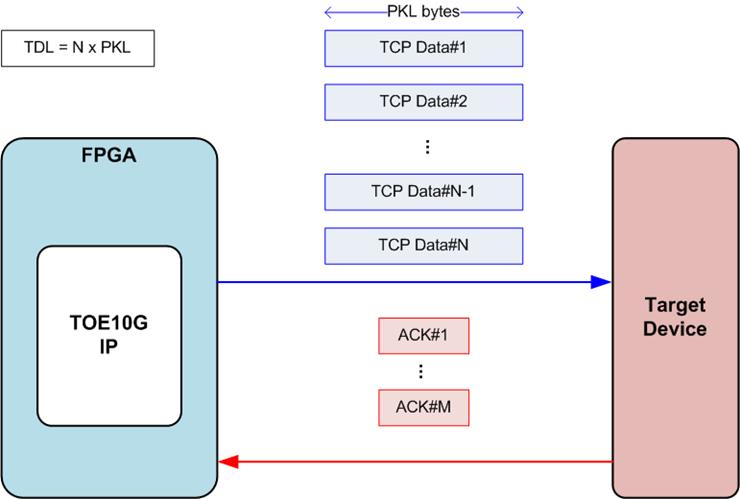
Figure 31: TCP packet when TDL = N times of PKL
When the TDL value matches N times the PKL value, the user data gets divided into N packets, transmitted to the target device, as shown in Figure 31. If the target device responds with an ACK packet for each TCP packet, the network system will contain N ACK packets. To optimize network performance, multiple ACK packets can be consolidated using the TCP delayed ACK technique into one packet. Therefore, the number of ACK packets returned from the target device (M) might be fewer than the data packets from the TOE10G IP (N) during the execution of the Send data command. The PSH[0] value does not affect this scenario. The last data packet (TCP Data#N) is transmitted only once.
TDL = N times of PKL + Residue
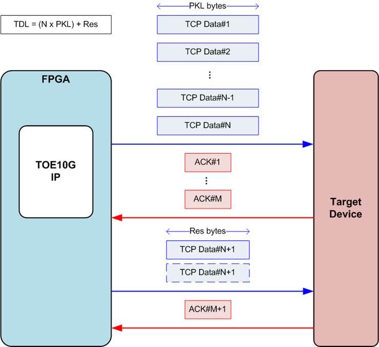
Figure 32: TCP packet when TDL = (N times of PKL) + Residue
Where TDL is not equal to N times of PKL value, the data transmitted to the target device is split into N packets of PKL-byte data along with one last packet containing Res-byte data, outlined in Figure 32. Initially, the process resembles the condition where TDL equals N times of PKL. The IP requires an ACK packet from the target device to confirm the complete reception of all N packets. Subsequently, the last packet carrying the residue byte data is sent. If the PSH[0] register is set to 0b (its default value), the residue packet is transmitted twice; otherwise, the last packet is sent just once. The Send data command concludes when the target returns an ACK to confirm that the last packet have been received.
Note: In situations where the target device operates on an OS enabling delayed ACK, the ACK#M packet, confirming the acceptance of TCP Data#N, might arrive late due to timeout condition in certain scenarios. Therefore, the target device should disable the delayed ACK feature or ensure alignment of the TDL to PKL value in systems sensitive to this latency time.
Connection Termination and Unusual Case
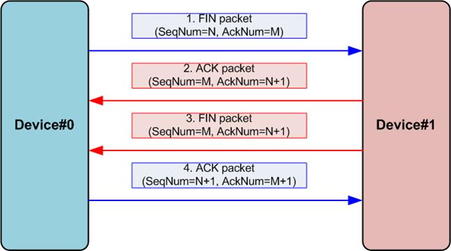
Figure 33: Terminate connection sequence
The process of terminating a connection in the standard scenario is illustrated in Figure 33, which shows the exchange of four packets between two devices. In this sequence, the first device (Device#0) initiates the connection termination by sending a FIN packet. If the second device (Device#1) agrees to terminate the connection, it responds with both an ACK and FIN packets, which may be combined into a single packet or transmitted separately. Finally, Device#0 confirms the termination by sending an ACK packet. However, this section describes the operation of the TOE10G IP in some unusual cases.
a) When the TOE10G IP receives an active close command from the user, it sends a FIN packet to commence the connection termination process. Subsequently, the TOE10G IP awaits FIN and ACK packets that contain specific values for the sequence number (SeqNum) and acknowledge number (AckNum). Assuming that a FIN packet emitted by the TOE10G IP assigns SeqNum=N and AckNum=M, the expected values for SeqNum and AckNum in the received FIN and ACK packets are M and N+1, respectively. If these expected packets are not received within the designated timeout period (set by the TMO register), without any retry attempts, the TOE10G IP transmits RST packet to terminate the connection. TimerInt and TMO[3] are also asserted to 1b.
b) Following the execution of an active close command operation, the TOE10G IP ceases to accept additional data from the target. Any received packet containing data is discarded, similar to the first case. The IP only accepts FIN and ACK packets that match the expected value of SeqNum and AckNum.
c) If the target initiates the connection termination by sending a FIN packet while the TOE10G IP still has remaining data for transmitting, the TOE10G IP accepts the termination request and halts data transmission. It responds with FIN and ACK packets to the target, with the SeqNum value configured to match the most recently confirmed data acceptance value. User can determine the amount of unsent data by monitoring the TDL register (RegDataA8 signal). Additional details of this case can be found in Figure 13.
Verification Methods
The TOE10G IP Core functionality was verified by simulation and also proved on real board design by using KC705/VC707/ZC706/KCU105/ZCU102/ZCU106/VCU118 evaluation board.
Recommended Design Experience
User must be familiar with HDL design methodology to integrate this IP into their design.
Ordering Information
This product is available directly from Design Gateway Co., Ltd. Please contact Design Gateway Co., Ltd. For pricing and additional information about this product using the contact information on the front page of this datasheet.
Revision History
|
Revision |
Date |
Description |
|
2.00 |
12-Jul-24 |
Add information of Fixed MAC customization and improve overall content |
|
1.14 |
19-Apr-21 |
Update PSH[0] description and add PKL/TDL setting in Send command topic |
|
1.13 |
2-Oct-20 |
Correct Figure3 and Figure4 |
|
1.12 |
26-Aug-20 |
Update company information |
|
1.11 |
24-Aug-20 |
Rename IP from TenGEMAC IP to 10G25GEMAC IP |
|
1.10 |
17-Jul-20 |
Add ZCU106 support and update Application details |
|
1.09 |
21-Aug-19 |
Add support VCU118 board and DG EMAC IP |
|
1.08 |
18-Jan-18 |
Add SRV register and rx_axis_tready signal |
|
1.07 |
23-Feb-17 |
Add KCU105 support and TCPRxFfLastRdCnt signal |
|
1.06 |
23-Dec-15 |
Update register to support readback |
|
1.05 |
3-Nov-15 |
Update read value of CMD[3:1] register |
|
1.04 |
20-Oct-15 |
Add PSH, WIN, and ETL register, and RegDataAx port |
|
1.03 |
14-Nov-14 |
Add ZC706 board support |
|
1.02 |
24-Sep-14 |
Update valid value of Rx Data Buffer in page7 |
|
1.01 |
9-Sep-14 |
Update IP to support full-duplex |
|
1.00 |
29-May-14 |
New release |