tCAMIP reference design by Search Replace function
Rev1.02 2-Jun-2023
2.2.2 Receive dataIn from test PC
2.3.4 tCAMIP searching process
3 tCAMIP Search Replace software on Test PC
3.2.3 Convert output array of character to output destination textbox string
3.3.1 alignEightFromText function
3.3.2 toeFifoTransfer function
1 Introduction
This document describes detailed reference design of tCAMIP for search/replace function via 10 Gigabit Ethernet. The contents including detailed of hardware design and software function.
The important hardware modules are “TOE10GIP_FIFO.vhd” and “SearchReplace.vhd” will be described in this document.
2 Hardware overview
Figure 2‑1 show reference design block diagram, that used 10 Gigabit Ethernet for communication between software on test PC and SearchReplace module in A10SoC/S10MX board.
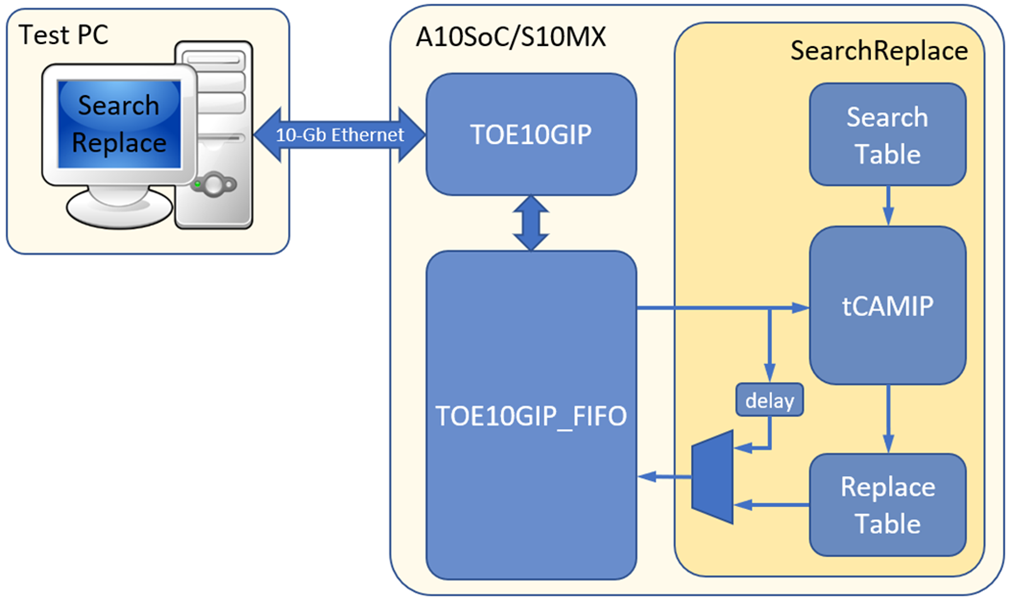
Figure 2‑1 Reference design block diagram
2.1 TOE10GIP
This part is contained TOE10GIP, TenGMacPhy, and MacRegCtrl modules. Please visit our website https://dgway.com/TOE10G-IP_A_E.html for more information.
2.2 TOE10GIP_FIFO
TOE10GIP_FIFO module is designed for 3 operations, 1st is initialized TOE10GIP, 2nd is passing every 64-bit data from TOE10GIP to SearchReplace module, 3rd is passing every 64-bit data from SearchReplace module to TOE10GIP. The signals are described as Table 2‑1
Table 2‑1 I/O signals
|
Signal |
Dir |
Description |
|
RstB |
In |
Reset module. Active Low. |
|
Clk |
In |
System clock. |
|
RegAddr[3:0] |
Out |
TOE10GIP Register address bus. |
|
RegWrData[31:0] |
Out |
TOE10GIP Register write data bus. Synchronous to RegAddr signal for write process. |
|
RegWrEn |
Out |
TOE10GIP Register write enable pulse. Synchronous to RegAddr and RegWrData signals. |
|
RegRdData[31:0] |
In |
TOE10GIP Register read data bus. |
|
Busy |
In |
TOE10GIP Busy flag is connected from signal RegDataA1(0). |
|
TCPRxFfRdCnt[12:0] |
In |
TOE10GIP Received buffer data counter to show total received data in the buffer as 64-bit unit. |
|
TCPRxFfRdEn |
Out |
TOE10GIP Received buffer read enable. Assert to ‘1’ to read data from Received buffer. |
|
TCPRxFfRdData[63:0] |
In |
TOE10GIP Received buffer read data bus. Valid in the next clock cycle after TCPRxFfRdEn is asserted to ‘1’. |
|
TCPTxFfWrEn |
Out |
TOE10GIP Transmit buffer write enable. Assert to ‘1’ to write data to Transmit buffer. |
|
TCPTxFfWrData[63:0] |
Out |
TOE10GIP Transmit buffer write data bus. Synchronous with TCPTxFfWrEn. |
|
dataInValid |
Out |
dataIn valid. Assert to ‘1’ when data is valid on dataIn. |
|
dataIn[63:0] |
Out |
dataIn bus. Synchronous with dataInValid. |
|
dataOutValid |
In |
dataOut valid. Assert to ‘1’ to write data to Transmit buffer. |
|
dataOut[63:0] |
In |
dataOut bus. Synchronous with dataOutValid. |
2.2.1 Initial TOE10GIP
After release RstB = ‘1’, TOE10GIP_FIFO start initial TOE10GIP by write all registers by count down rSequence as Table 2‑2. After that when Busy signal from TOE10GIP is ‘0’, it means TOE10GIP is ready to communication. Figure 2‑2 show timing diagram of register writing for initial TOE10GIP.
Table 2‑2 Sequence of initialized register writing
|
rSequence |
RegAddr |
RegWrData |
Description |
|
B |
0000b |
0x00000001 |
active soft reset of TOE10GIP to be '1' |
|
A |
1110b |
0x00000000 |
set TOE10GIP to be client mode |
|
9 |
1100b |
0x00000000 |
set not enable window update feature |
|
8 |
1001b |
0x00006000 |
set timeout value to 0x00006000 |
|
7 |
0111b |
0x0000EA60 |
set source port number to 60000 |
|
6 |
0110b |
0x0000EA61 |
set destination port number to 60001 |
|
5 |
0101b |
0xC0A80750 |
set source IP to 192.168.7.80 |
|
4 |
0100b |
0xC0A80751 |
set source IP to 192.168.7.81 |
|
3 |
0011b |
0x00001122 |
set 16-bit upper MAC address to 0x1122 |
|
2 |
0010b |
0x33445566 |
set 32-bit lower MAC address to 0x33445566 |
|
1 |
0000b |
0x00000000 |
release soft reset of TOE10GIP to be '0' |
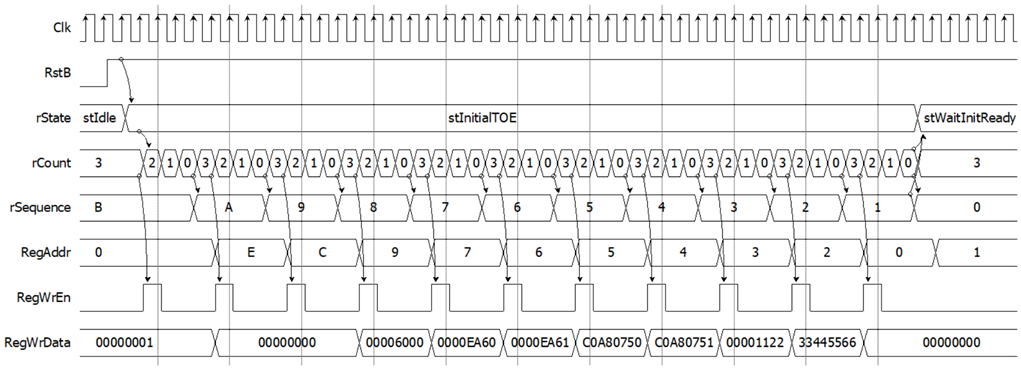
Figure 2‑2 Timing diagram of register writing for initial TOE10GIP
2.2.2 Receive dataIn from test PC
When TOE10GIP received packet data from test PC, the TCPRxFfRdCnt is increased to be not zero. TOE10GIP_FIFO start read data from TOE10GIP with number of TCPRxFfRdCnt. Then dataIn valid and dataInValid is active at next cycle from TCPRxFfRdEn signal. Figure 2‑3 show detailed timing diagram of Receive 8x64-bit dataIn from TOE10GIP.
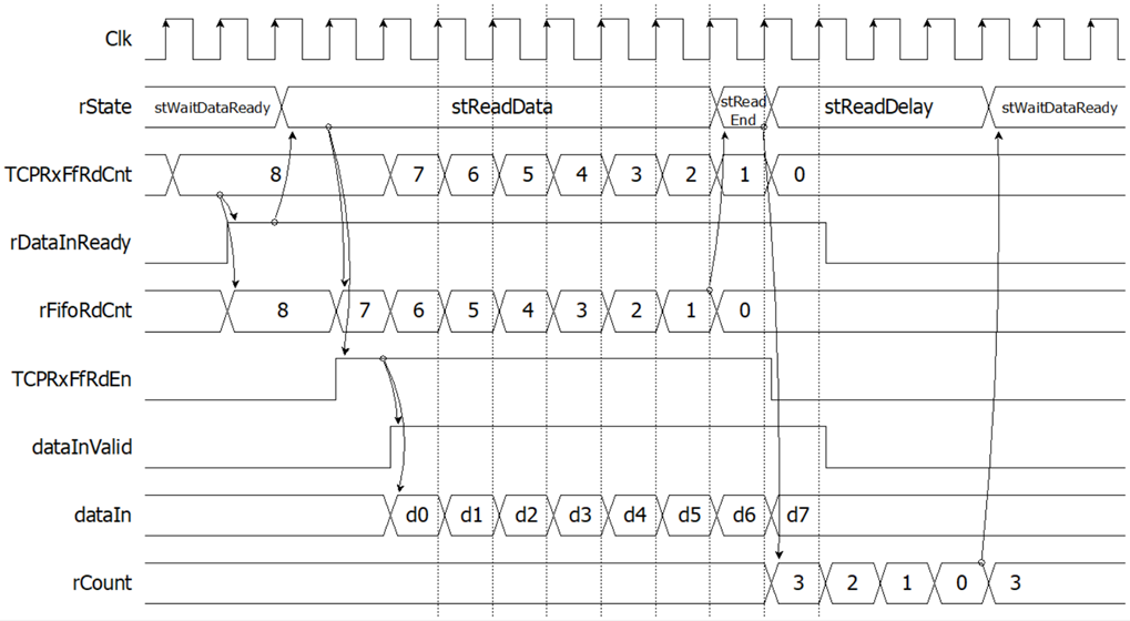
Figure 2‑3 Timing diagram of receive 8x64-bit dataIn from TOE10GIP
2.2.3 Send dataOut to test PC
When dataOutValid and dataOut is directly connect to TCPTxFfWrEn and TCPTxFfWrData
respectively. TOE10GIP_FIFO is designed to detect at the end of data when dataOutValid is changed from ‘1’ to ‘0’. TOE10GIP_FIFO will write data count (rFifoWrCount) to TDL register, then write 0x00000000 to CMD register of TOE10GIP for transfer data to test PC. Figure 2‑4 show detailed timing diagram of Send 8x64-bit dataOut to TOE10GIP.
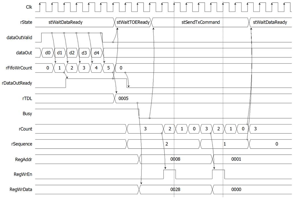
Figure 2‑4 Timing diagram of send 8x64-bit dataOut to TOE10GIP
2.3 Search Replace module
Search Replace module is designed to search 64-bit dataIn in Search Table. When dataIn is matched in Search Table, dataOut is assigned with replace word from Replace Table. But if dataIn is not matched in Search Table (resultData=0), the dataIn is assigned to dataOut instead.
2.3.1 Search Table
Search Table is dual port RAM, 8K address x 9-bit width. This table is assigned to be rule table for tCAMIP.
Port A is reserved for future used.
Port B is connected with tCAMIP as shown in Table 2‑3.
ruleCount(3) is designed to generate 1 clock cycle pulse delay from ruleRdReq signal and is assigned to be ruleRdValid signal. Figure 2‑5 show timing diagram of ruleRdValid generation.
Table 2‑3 Port B signal mapping of search table
|
Search Table signals |
Dir |
tCAMIP signals |
|
src_wren_b |
<= |
'0' |
|
src_data_b |
<= |
(others => '0') |
|
src_address_b |
<= |
ruleAddr |
|
q_b |
=> |
ruleData |
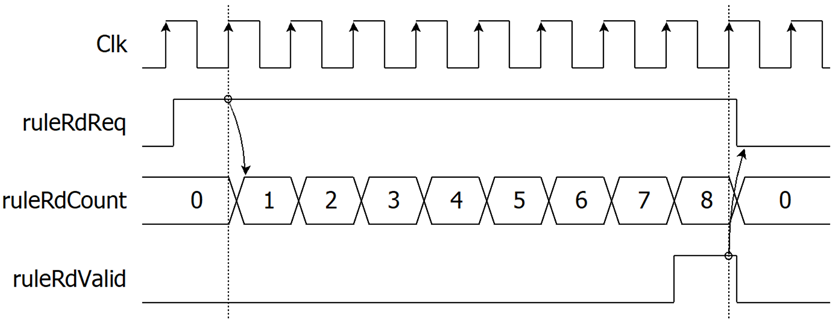
Figure 2‑5 Timing diagram of ruleRdValid generation
Each 8-byte ASCII code of search word is assigned as 8 x 9-bit rule. The “don’t care” byte is assigned as [x], 0x100 value. Table 2‑4 shows sample conversion from search word to rule table. Search Table is initialed values with file “search.mif”.
Table 2‑4 Sample of search word conversion to rule table memory
|
Rule No. |
Search word |
Address |
A+0 |
A+1 |
A+2 |
A+3 |
A+4 |
A+5 |
A+6 |
A+7 |
|
0001 |
white |
0000 |
‘w’, 077 |
‘h’, 068 |
‘i’, 069 |
‘t’, 074 |
‘e’, 065 |
‘ ’, 020 |
[x], 100 |
[x], 100 |
|
0002 |
White |
0008 |
057 |
068 |
069 |
074 |
065 |
020 |
100 |
100 |
|
0003 |
nurse |
0010 |
06E |
075 |
072 |
073 |
065 |
020 |
100 |
100 |
|
0004 |
worse |
0018 |
077 |
06F |
072 |
073 |
065 |
020 |
100 |
100 |
|
0005 |
horse |
0020 |
068 |
06F |
072 |
073 |
065 |
020 |
100 |
100 |
|
0006 |
Horse |
0028 |
048 |
06F |
072 |
073 |
065 |
020 |
100 |
100 |
|
0007 |
Worse |
0030 |
057 |
06F |
072 |
073 |
065 |
020 |
100 |
100 |
|
0008 |
noise |
0038 |
06E |
06F |
069 |
073 |
065 |
020 |
100 |
100 |
|
0009 |
three |
0040 |
074 |
068 |
072 |
065 |
065 |
020 |
100 |
100 |
|
000A |
city |
0048 |
063 |
069 |
074 |
079 |
020 |
100 |
100 |
100 |
|
000B |
duty |
0050 |
064 |
075 |
074 |
079 |
020 |
100 |
100 |
100 |
|
000C |
City |
0058 |
043 |
069 |
074 |
079 |
020 |
100 |
100 |
100 |
|
000D |
Duty |
0060 |
044 |
075 |
074 |
079 |
020 |
100 |
100 |
100 |
|
000E |
busy |
0068 |
062 |
075 |
073 |
079 |
020 |
100 |
100 |
100 |
|
000F |
easy |
0070 |
065 |
061 |
073 |
079 |
020 |
100 |
100 |
100 |
|
0010 |
Busy |
0078 |
042 |
075 |
073 |
079 |
020 |
100 |
100 |
100 |
|
0011 |
bury |
0080 |
062 |
075 |
072 |
079 |
020 |
100 |
100 |
100 |
|
… |
|
|
|
|
|
|
|
|
|
|
Note: All numbers are hex number.
2.3.2 Initial State Machine
This reference design is provided simple state machine to initialize tCAMIP. Figure 2‑6 show timing diagram of Initial State Machine to generate ruleInit signal and check ruleBusy and ruleStatusCode signals. Operation of initialization is described as below.
· When RstB is active (‘0’), rState is set to stIdle.
· When RstB is released (‘1’), rState is changed to stInitStart.
· At stInitStart, rState is changed to stWaitReady when ruleBusy is active from tCAMIP.
· At stWaitReady, rState is changed to stInitCompleted when ruleBusy is released to zero and ruleStatusCode is 0001b (initial completed).
o In case that ruleBusy is released to zero but ruleStatusCode is not 0001b, it means tCAMIP initialization is not success. rState is changed to stIdle for restart initial process again.
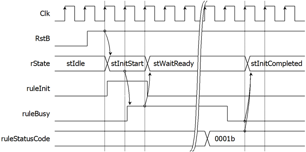
Figure 2‑6 Timing diagram of Initial State Machine
2.3.3 Replace Table
Replace Table is dual port RAM, 1K address x 64-bit width. This table is assigned with replace word. The relation between search word, replace word and memory data is shown as in
Table 2‑6. Replace Table is initialed values with file “replace.mif”
According to resultData from tCAMIP is mapping with Rule No., then address of replace word can be calculated by resultData minus 1 (rep_address_b <= resultData – 1). The detailed of signals assignment is shown as below.
Port A is reserved for user logics.
Port B is connected with signals as shown in Table 2‑5.
Table 2‑5 Port B signal mapping of replace table
|
Replace Table signals |
Dir |
tCAMIP signals |
|
rep_wren_b |
<= |
'0' |
|
rep_data_b |
<= |
(others => '0') |
|
rep_address_b |
<= |
resultData - 1 |
|
rep_q_b |
=> |
rep_q_b |
Table 2‑6 Sample of search word conversion to rule table memory
|
Rule No. |
Search word |
Replace word |
Address |
Replace word (hex) |
|
0001 |
white |
word001 |
0000 |
2031303064726F77 |
|
0002 |
White |
word002 |
0001 |
2032303064726F77 |
|
0003 |
nurse |
word003 |
0002 |
2033303064726F77 |
|
0004 |
worse |
word004 |
0003 |
2034303064726F77 |
|
0005 |
horse |
word005 |
0004 |
2035303064726F77 |
|
0006 |
Horse |
word006 |
0005 |
2036303064726F77 |
|
0007 |
Worse |
word007 |
0006 |
2037303064726F77 |
|
0008 |
noise |
word008 |
0007 |
2038303064726F77 |
|
0009 |
three |
word009 |
0008 |
2039303064726F77 |
|
000A |
city |
word010 |
0009 |
2030313064726F77 |
|
000B |
duty |
word011 |
000A |
2031313064726F77 |
|
000C |
City |
word012 |
000B |
2032313064726F77 |
|
000D |
Duty |
word013 |
000C |
2033313064726F77 |
|
000E |
busy |
word014 |
000D |
2034313064726F77 |
|
000F |
easy |
word015 |
000E |
2035313064726F77 |
|
0010 |
Busy |
word016 |
000F |
2036313064726F77 |
|
0011 |
bury |
word017 |
0010 |
2037313064726F77 |
|
… |
|
|
|
|
2.3.4 tCAMIP searching process
Figure 2‑7 shows timing diagram of searching data path. The detailed operation of searching process is described as below.
After tCAMIP initialization is completed by initial process on topic 2.3.2, In every clock cycle, dataIn will be searching by tCAMIP and set resultData as matched Rule No. by latency 7 clock cycles.
rep_address_b (resultData – 1) from tCAMIP is used for address of Replace Table, then rep_q_b is out from Replace Table after 2 clock cycles because Replace Table memory is generated with both registers of input address port and output port.
rSearchMatch(0) is set to ‘1’ when resultData from tCAMIP is zero (not match). Then rSearchMatch(1) is one clock cycle delay from rSearchMatch(0).
To control timing of input dataIn and rep_q_b in the same clock cycle, dataIn8 is 9 clock cycles delay from dataIn signals, then dataIn8 and rep_q_b is valid in the same clock cycle.
rLongWord is set to be ‘1’ when previous cycle of dataIn8[63:56] (last byte of word) is 0x20 (space bar character).
Then dataOut is register output multiplexer that is assigned with rep_q_b when rLongWord=’0’ and rSearchMatch(1)=’1’, else is assigned with dataIn8.
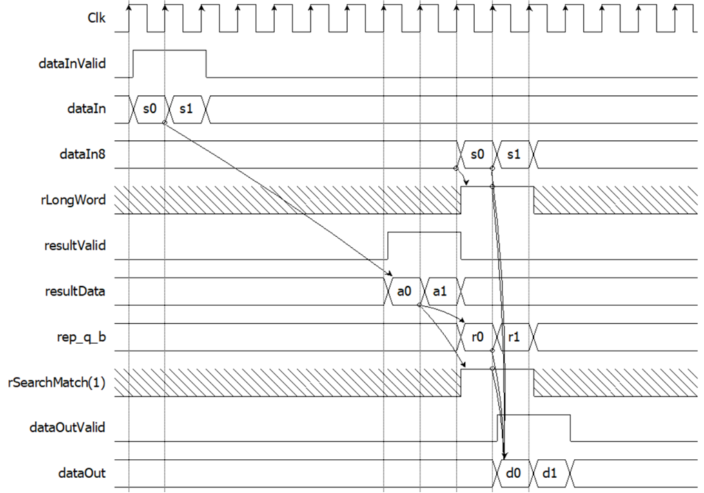
Figure 2‑7 Timing diagram of searching data path
3 tCAMIP Search Replace software on Test PC
Main function is separated into 3 parts, 1st is connect/disconnect button with A10SoC/S10MX board. 2nd is Software Replace button. 3rd is tCAMIP Replace button. The user interface is shown as Figure 3‑1
Software Replace button and tCAMIP Replace button is designed with the same function by search and replace words from input source text to show replace words in output destination text.
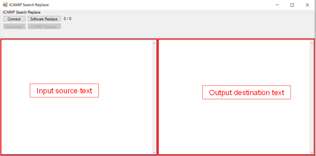
Figure 3‑1 tCAMIP Search Replace software
3.1 Connect/Disconnect button
When user click connect button, software will open connection to A10SoC/S10MX board at IP=192.168.7.80 port=60000.
In the other hand, disconnect button is used to disconnect from A10SoC/S10MX board.
3.2 Software Replace button
This button called softSearchReplace function where is designed to search and replace word by “replaceTable” dictionary. The software operation can be explained in 4 parts as below.
3.2.1 Split all text by space
The first step, software will split string from input source text into array of strings by below syntax.
3.2.2 Search Replace Loop
For loop with number of split words, is used to search each word. In case that split word is not found in replaceTable dictionary, split word is concatenated in output array of characters. In another case that split word is found in replaceTable dictionary, replace word is concatenated in output array of characters.instead.
3.2.3 Convert output array of character to output destination textbox string
When loop is finished, output array of character is converted to string type and show into output destination textbox string as below syntax.
3.2.4 Show operation time.
At the end of this function will show popup message for text size and operation time.
3.3 tCAMIP Replace button
This button called tCAMIPSearchReplace function where is designed to search and replace word by using tCAMIP on A10SoC/S10MX do instead of software. The software operation can be explained in 4 parts as below.
3.3.1 alignEightFromText function
According to TOE10GIP need to data alignment with 64-bit data, this function is designed to add ‘space’ character (ASCII = 0x20) between each word to align with 64-bit data.
Table 3‑1 alignEightFromText function
|
(int, byte[]) alignEightFromText(string text) |
|
|
Parameters |
string: input source text |
|
Return value |
int: size of return buffer byte[]: return buffer |
|
Description |
This function will add ‘space’ character to align each word with 64-bit data. |
3.3.2 toeFifoTransfer function
According to tCAMIP will do search replace function in this reference design. So toeFifoTransfer is designed to transmit/receive 64-bit aligned buffer data to/from A10SoC/S10MX board.
Table 3‑2 toeFifoTransfer function
|
(int, int, byte[]) toeFifoTransfer(int size, byte[] buffer) |
|
|
Parameters |
int: size of transmit buffer byte[]: transmit buffer |
|
Return value |
int: count of transmit via ethernet int: count of receive via ethernet byte[]: receive buffer |
|
Description |
This function repeat transmits and receives block of data to A10SoC/S10MX board. Maximum size of each block is 32K to avoid buffer full at TOE10GIP. |
3.3.3 trimBuffer function
According topic 3.3.1, software adds ‘space’ to input source text to align with 64-bit data. So trimBuffer function is designed to remove the additional ‘space’ from receive buffer, then convert from array of byte to be string type.
Table 3‑3 trimBuffer function
|
string trimBuffer(int size, byte[] buffer) |
|
|
Parameters |
int: size of receive buffer byte[]: receive buffer |
|
Return value |
string: output destination text |
|
Description |
This function will replace multiple space with one space. |
3.3.4 Show operation time.
At the end of this function will show popup message for text size and operation time.
4 Revision History
|
Revision |
Date |
Description |
|
1.02 |
5-Mar-2021 |
Revise |
|
1.01 |
29-Dec-2020 |
Additional support for S10MX board. |
|
1.00 |
25-Aug-2020 |
Initial version release |