FPGA Setup for NVMe-IP Series Demo
1 Overview
This document outlines the required setup for running NVMe-IP series demo on FPGA development board. The demo setup involves connecting an NVMe SSD through an adapter board and utilizing the Serial console on a PC as the user interface console.
2 Environment Requirements
To successfully run the demo, ensure the following components are prepared:
1) Supported FPGA development boards:
· PCIe Gen4 (Hard IP): VCK190, VHK158, Alveo-U50
· PCIe Gen4 (Soft IP): KCU116, ZCU102, ZCU106, VCU118
· PCIe Gen3 (Hard IP): KCU105, KCU116, ZCU106, VCU118, ZCU111
· PCIe Gen3 (Soft IP): KCU105, KCU116, ZCU102, ZCU106, VCU118
· PCIe Gen2: AC701, ZC706, VC707
2) A PC installing FPGA programmer software (Vivado) and a Serial console such as HyperTerminal or TeraTerm.
3) PCIe adapter boards provided by Design Gateway: https://dgway.com/ABseries_E.html
· AB17-M2FMC: M.2-FMC adapter board for NVMe-IP evaluation
· AB18-PCIeX16: PCIe x16 Lanes Crossover adapter board for NVMe-IP evaluation
· AB19-M2PCI: M.2-PCIe adapter board for NVMe-IP evaluation
· AB20-U2PCI: U.2/U.3-PCIe adapter board for NVMe-IP evaluation
4) Power adapter for the FPGA development board.
5) ATX power supply for the PCIe adapter board.
6) NVMe SSD connected to the PCIe adapter board. Ensure that the SSD’s PCIe speed is compatible with the NVMe-IP demo requirements.
7) USB cable for JTAG programming and Serial console:
· Versal boards : One USB Type-C cable
· Alveo boards : Alveo programming cable with micro USB cable
· UltraScale/UltraScale+ boards : One or two USB cables
· 7-Series boards : One micro USB cable and one mini USB cable
Versal board
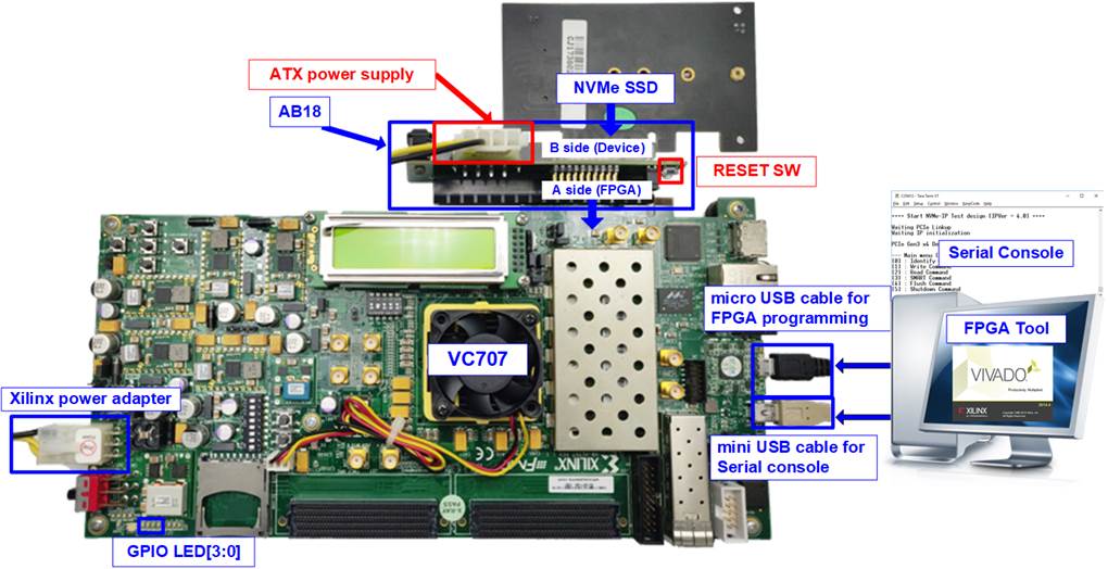
Figure 1 NVMe-IP Series Demo Setup on VHK158 with AB19

Figure 2 NVMe-IP Series Demo Setup on VHK158 with AB20
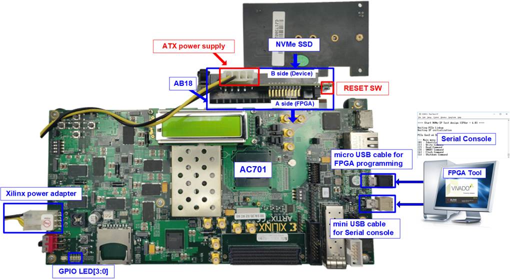
Figure 3 NVMe-IP Series Demo Setup on VCK190 with AB18
Zynq UltraScale+ board
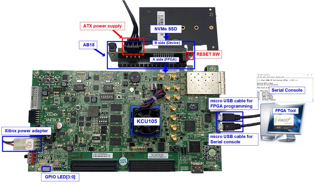
Figure 4 NVMe-IP Series Demo Setup on ZCU111 with AB17
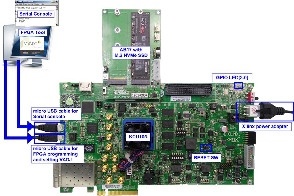
Figure 5 NVMe-IP Series Demo Setup on ZCU106 with AB17
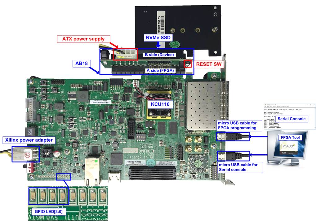
Figure 6 NVMe-IP Series Demo Setup on ZCU106 with AB18
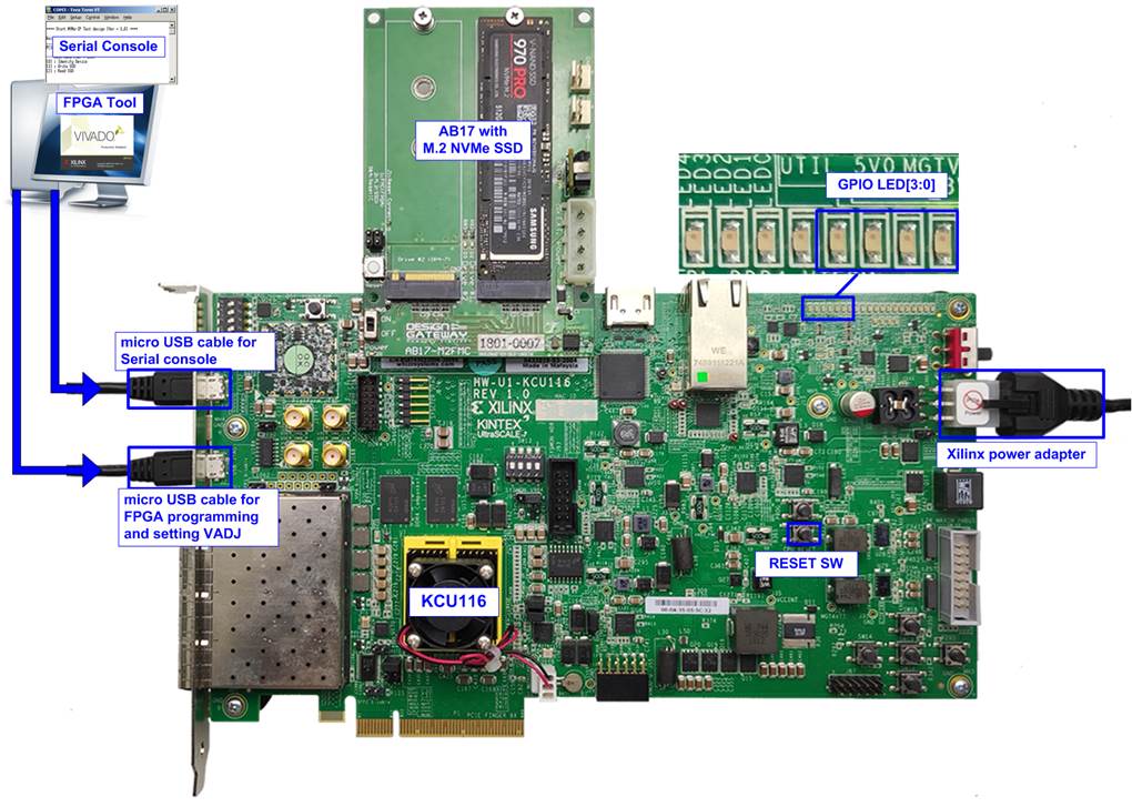
Figure 7 NVMe-IP Series Demo Setup on ZCU102 with AB17
Alveo card

Figure 8 NVMe-IP Series Demo Setup on Alveo-U50 with Customized AB18
UltraScale+ board

Figure 9 NVMe-IP Series Demo Setup on VCU118 with AB17
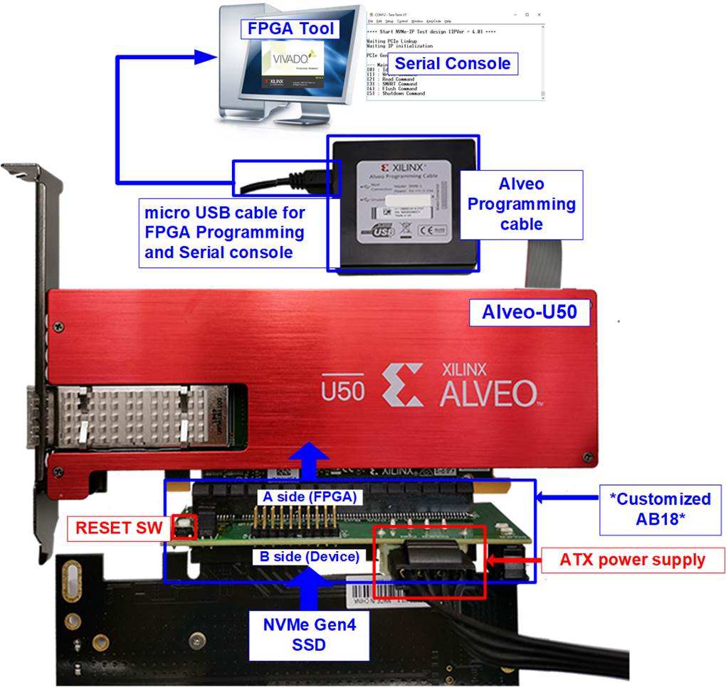
Figure 10 NVMe-IP Series Demo Setup on VCU118 with AB18
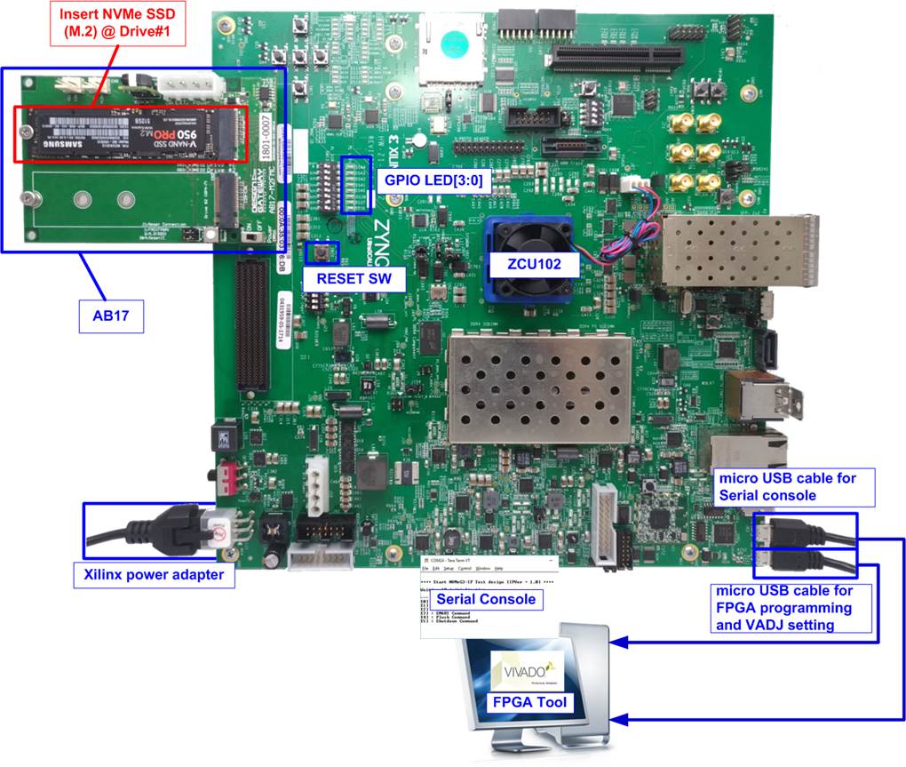
Figure 11 NVMe-IP Series Demo Setup on KCU116 with AB17
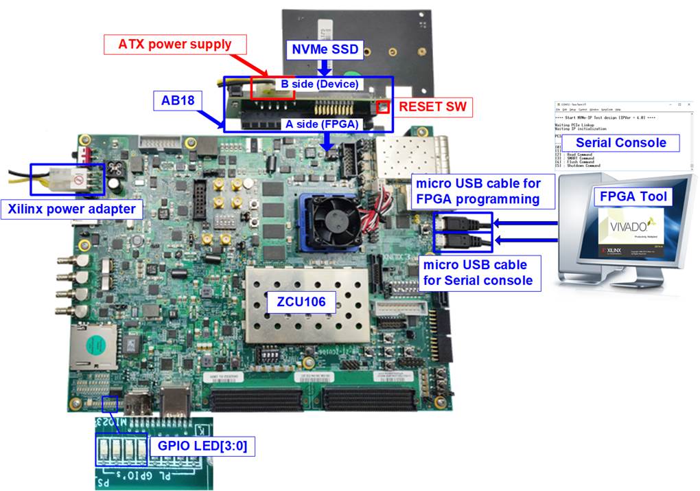
Figure 12 NVMe-IP Series Demo Setup on KCU116 with AB18
UltraScale board

Figure 13 NVMe-IP Series Demo Setup on KCU105 with AB17

Figure 14 NVMe-IP Series Demo
Setup on KCU105 with AB18
7-series board
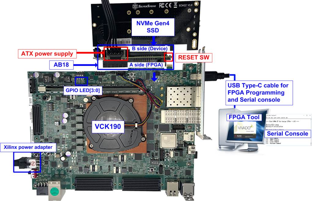
Figure 15 NVMe-IP Series Demo Setup on AC701
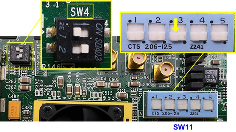
Figure 16 NVMe-IP Series Demo Setup on ZC706
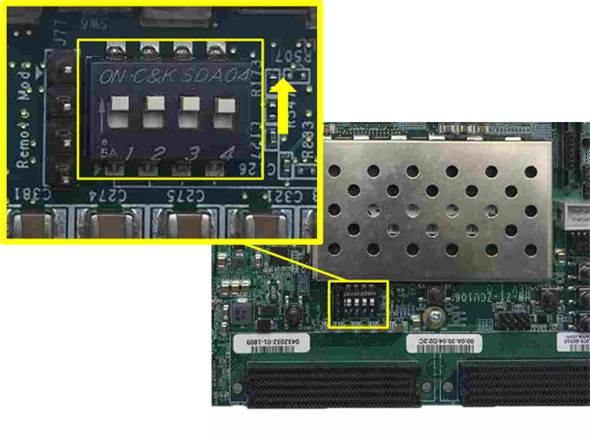
Figure 17 NVMe-IP Series Demo Setup on VC707
3 Demo Setup
3.1 Board Setup
Follow these steps to set up the board for the demo.
1) Power off the system.
2) Check DIP switch on FPGA board settings for JTAG configuration on Zynq and Versal boards.
· For ZC706 board, set SW11=all OFF to configure PS from JTAG and set SW4[1:2]=[OFF ON] to connect JTAG with USB-to-JTAG interface, as shown in Figure 18.
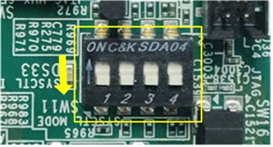
Figure 18 SW4 and SW11 Settings to Configure PS from JTAG on ZC706
· For ZCU106/ZCU102/ZCU111 board, set SW6=all ON to configure PS from JTAG, as shown in Figure 19.

Figure 19 SW6 Setting to Configure PS from JTAG on ZCU106
· For VCK190 board, set SW11=all OFF in order not to use micro-SD card to boot, as shown in Figure 20.
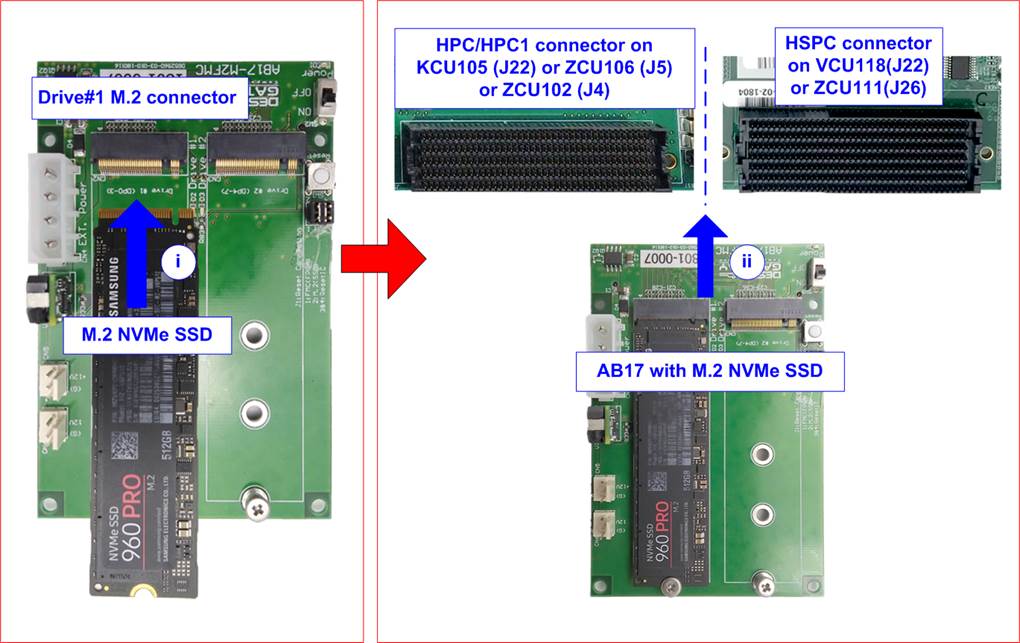
Figure 20 SW11 Setting on VCK190
· For VHK158 board, set SW1=all ON and SW3[1:0]=OFF, ON.
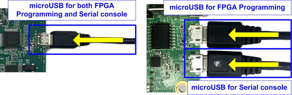
Figure 21 SW1 and SW3 Setting on VHK158
3) Prepare the NVMe SSD and the appropriate PCIe adapter board based on your hardware configuration.
AB17-M2FMC
i) Connect M.2 NVMe SSD to Drive#1 M.2 connector on AB17-M2FMC.
ii) Connect AB17-M2FMC to HPC/HPC1 connector on KCU105(J22), ZCU106(J5), ZCU102(J4), or HSPC on VCU118(J22), ZCU111(J26), as shown in Figure 22.
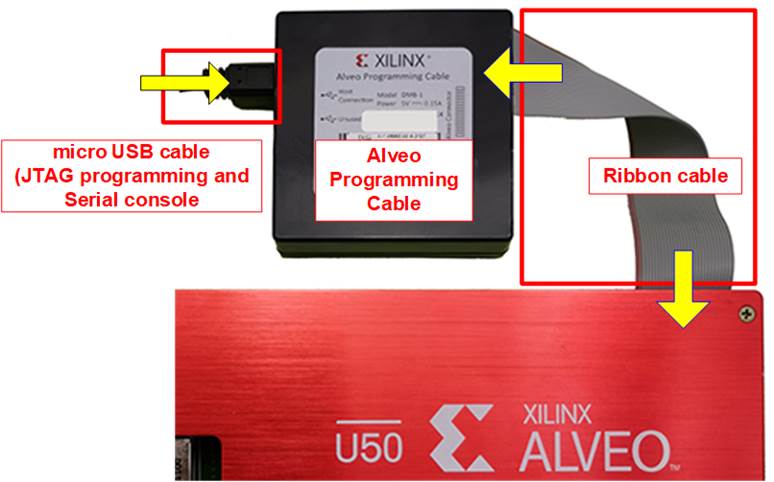
Figure 22 AB17-M2FMC Connection Setup
AB18-PCIeX16 or customized AB18 (Alveo-U50 card)
i) Confirm that two mini jumpers are inserted at J5 connector on AB18.
ii) Connect ATX power supply to AB board.
iii) Connect PCIe connector on FPGA board/Alveo card to FPGA Side (A-side) and connect NVMe PCIe SSD to device side (B-side) on AB board, as shown in Figure 23.
Warning: Please confirm that the SSD is correctly inserted into the B-side of the AB18 (not the A-side) before powering on the system.
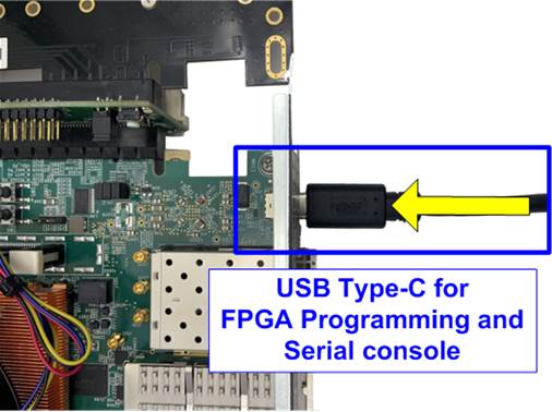
Figure 23 AB18-PCIeX16 Connection Setup
AB19-M2PCI
i) Confirm that two mini jumpers are inserted at JP1, specifically between pins 1-3 and 2-4.

Figure 24 Jumper on AB19
ii) Connect the NVMe SSD to the AB19 board.
VHK158 : Connect to CN2 for PCIe Lane 7-4 on the AB19 board.
Others : Connect to CN1 for PCIe Lane 3-0 on the AB19 board.
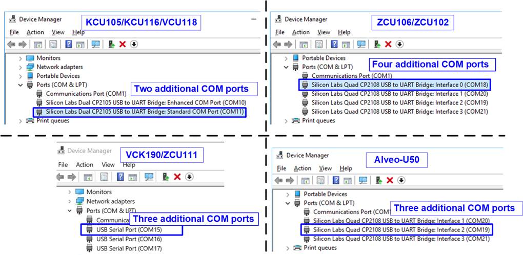
Figure 25 Connect the NVMe SSD to AB19
iii) Connect the 6-Pin PCIe AUX power cable from the ATX power supply to the AB19 board.
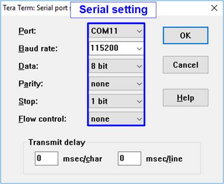
Figure 26 Connect 6-Pin PCIe Power Supply to AB19
iv) Insert the AB19 into the PCIe connector on the FPGA board.

Figure 27 Connect AB19 to FPGA Board
v) Adjust the height of the AB19 by sliding the support board up or down until the AB19 is aligned with the PCIe connector on the FPGA board. Once aligned, tighten the wing nut to fix the height.

Figure 28 Adjust the Height of AB19 Support Board
AB20-U2PCI
i) Ensure that the two mini jumpers at JP1 on AB20 are inserted between pins 1-4 and 2-3.
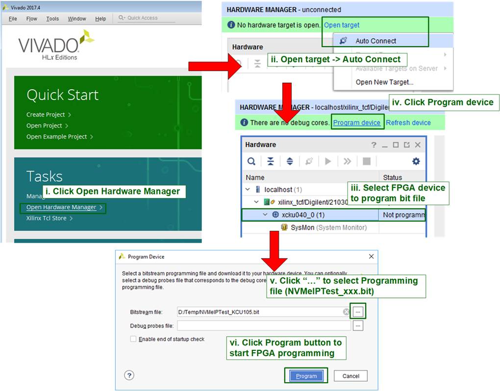
Figure 29 Jumpers on AB20
ii) Connect the NVMe SSD to the AB20 board.
VHK158 : Connect to CN2 for PCIe Lane 7-4 on the AB20 board.
Others : Connect to CN1 for PCIe Lane 3-0 on the AB20 board.

Figure 30 Connect U.2/U.3 NVMe SSD to AB20
iii) Connect 6-pin PCIe AUX power cable from the ATX power supply to the AB20 board.
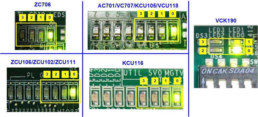
Figure 31 Connect 6-Pin PCIe Power Supply to AB20
iv) Insert the AB20 into the PCIe connector on the FPGA board. Adjust the height of the FPGA board to align with the PCIe connector on the AB20-U2PCI adapter board.
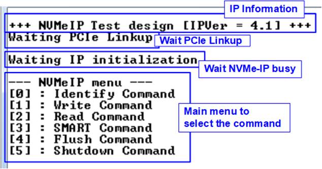
Figure 32 Connect AB20 to FPGA Board and Adjust Height of FPGA Board
4) Connect USB cables for JTAG programming and Serial console.
· For 7-series board, connect micro-USB cable for JTAG and mini-USB cable for Serial console.
· For UltraScale/UltraScale+ board:
ZCU111 : Connect a micro-USB cable for both JTAG and Serial console.
Others : Connect two micro-USB cables for JTAG and Serial console.

Figure 33 Micro USB Cable Connection
· For Alveo-U50, connect a Ribbon cable to attach the Alveo programming cable to Alveo-U50 board, and a micro-USB cable for JTAG and Serial console, as shown in Figure 34.
Note: More details about Alveo programming cable are described in the user guide.
https://docs.amd.com/r/en-US/ug1377-alveo-programming-cable-user-guide

Figure 34 Alveo Programming Cable
· For Versal board, connect USB Type-C for JTAG and Serial console.
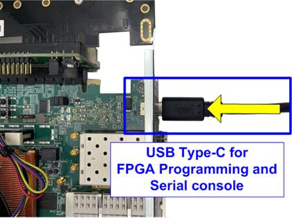
Figure 35 USB Type-C Cable Connection
5) Connect the power adapter to the FPGA board.
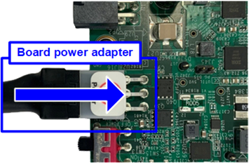
Figure 36 Connect Power Adapter to FPGA Board
3.2 File Programming
Follow these steps to program the demo file into the FPGA board.
1) Connect the USB cable from the FPGA board to the PC. An additional COM port is detected.
· KCU105/KCU116/VCU118: Select Standard COM port.
· ZCU106/ZCU102/ZCU111/VCK190/VHK158: Select the lowest number of additional COM ports.
· Alveo-U50: Select number#2 of the additional COM ports.
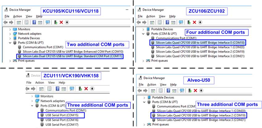
Figure 37 Additional COM Port when USB Cable is Plugged In
On Serial console, set Baud rate=115,200, Data=8-bit, Non-Parity, and Stop=1, as shown in Figure 38.
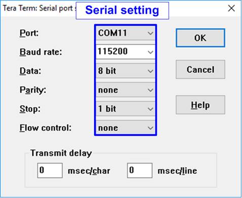
Figure 38 Serial Console Setting
2) Turn on the power to the FPGA board, PCIe adapter board, and ATX power supply.
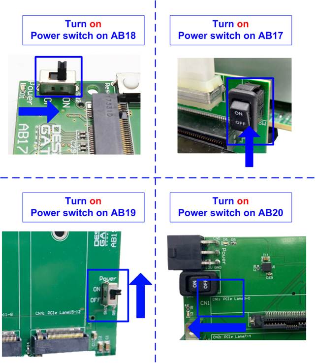
Figure 39 Turn On Power Switch on Adapter Board
3) For VHK158 board, open the Serial console for monitoring the boot-up message by selecting the third port. The console settings are similar to the previous console (baud rate=115,200 Data=8 bit Non-Parity Stop=1). Wait until the boot message on the console is completed, then close the boot-up message Serial console.
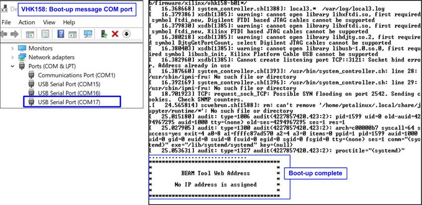
Figure 40 Boot-up Message of Power-on Sequence on VHK158
4) When using AB17-M2FMC connection on KCU105 or VCU118 board, user must set VADJ on FMC connector as following steps.
KCU105 board
Open Serial console to connect with Enhanced COM port (baud rate=115,200 Data=8 bit Non-Parity Stop=1). The console shows System Controller menu, as shown in Figure 41.
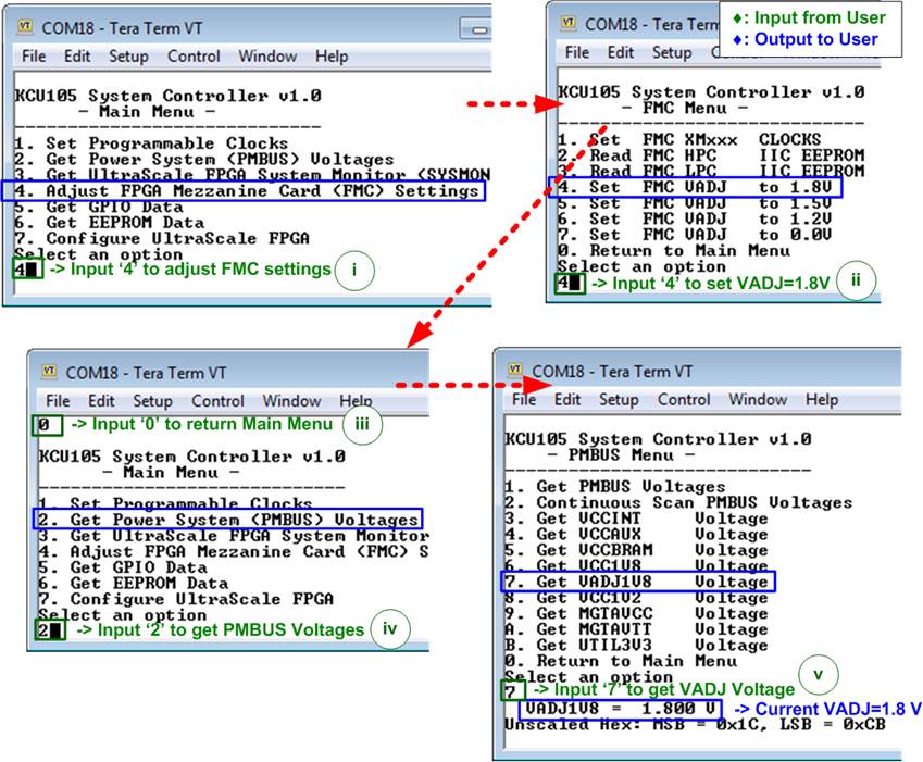
Figure 41 Setting VADJ of FMC on KCU105
To set VADJ of FMC to 1.8V, the following steps are recommended.
i) Input ‘4’ to select Adjust FMC Settings.
ii) Input ‘4’ to set FMC VADJ to 1.8V.
iii) Input ‘0’ to return to Main Menu.
iv) Input ‘2’ to get PMBUS Voltages.
v) Input ‘7’ to get VADJ1V8 Voltage. The output voltage of this menu must be equal to 1.8V to confirm that VADJ has been set completely.
For more details of System Controller, please check “UG917 KCU105 Board User Guide” in section “Appendix C: System Controller.
https://docs.amd.com/v/u/en-US/ug917-kcu105-eval-bd
VCU118 board
Open SCUI.exe and run following steps.
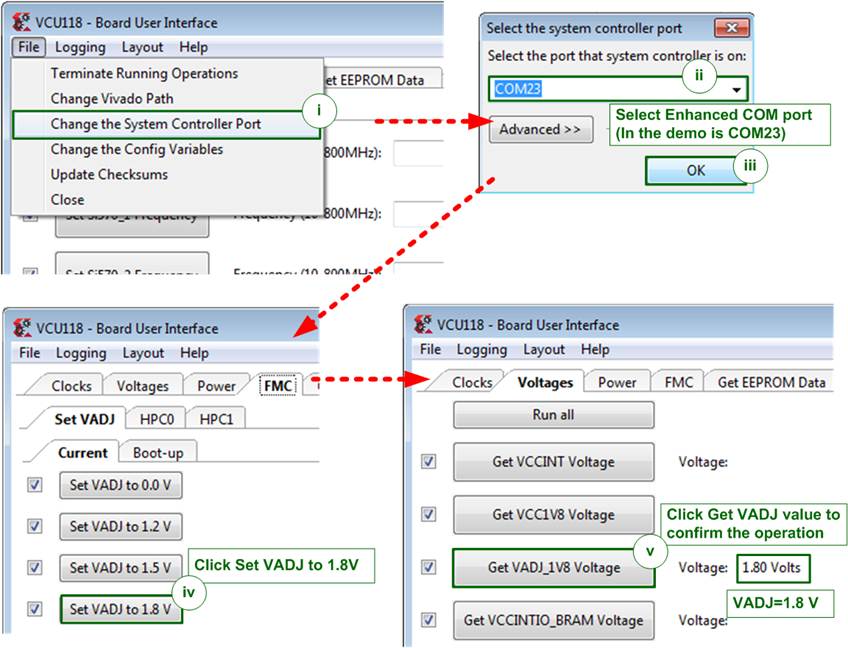
Figure 42 Setting VADJ of FMC for VCU118
i) Select File->Change the System Controller Port.
ii) Select COM port number which is Enhanced COM Port.
iii) Click “OK” button to confirm the port.
iv) Select FMC tab -> Set VADJ tab -> Current tab. Click “Set VADJ to 1.8V” button.
v) Select Voltages tab and click “Get VADJ_1V8 Voltage” button. The output voltage must be equal to 1.8V to confirm that VADJ has been set completely.
System controller tool (SCUI.exe) can be downloaded from AMD website.
https://www.xilinx.com/products/board-docs/vcu118-docs.html
Direct link for SCUI.exe on Vivado2017.4.
5) Download and program the configuration file and firmware to the FPGA board.
Non-SoC Boards
Configure FPGA by using Vivado tool, as shown in Figure 43.
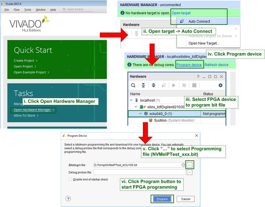
Figure 43 Program FPGA by Vivado
SoC Boards (Zynq-7000, Zynq-UltraScale+, and Versal)
Open Vivado TCL shell and run the bat file of the NVMeIPTest, as shown in Figure 44.
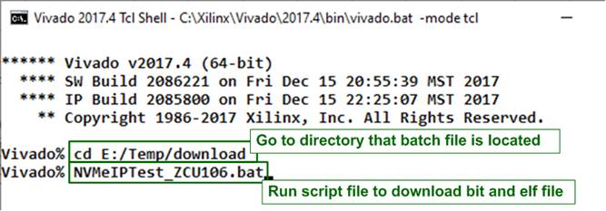
Figure 44 Command Script to Download Demo File on Vivado TCL Shell
6) Check LED status on FPGA board. The description of LED is as follows in Table 1.
Note: There is no LED status on Alveo card.
Table 1 LED Definitions
|
GPIO LED |
ON |
OFF |
|
0 |
Normal operation |
Clock is not locked, or reset button is pressed |
|
1/R |
System is busy |
Idle status |
|
2/C |
IP Error detected |
Normal operation |
|
3/L |
Data verification fails |
Normal operation |
7) After programming is completed, LED[0] and LED[1] are ON during PCIe initialization process. Then, LED[1] changes to OFF after PCIe completes initialization process.
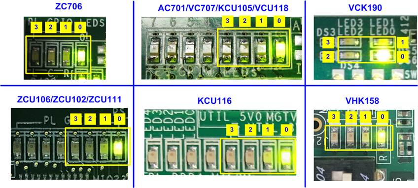
Figure 45 LED Status After Loading Configuration File and Completing Initialization
8) The main menu is displayed on Serial console. Now it is ready to receive commands from the user.
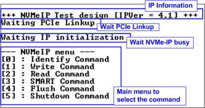
Figure 46 Main Menu After IP Finishes Initialization
4 Customized AB18 Board
This topic describes the process for modifying the AB18-PCIeX16 to connect with the Alveo card and NVMe SSD. Once completely modified, the customized AB18 board should only be connected to the Alveo card. Connecting the customized AB18 to other AMD development kits may result in board damage due to power supply collisions. The steps for modifying the AB18 are outlined below.
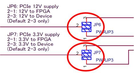
Figure 47 JP6 and JP7 Modification on AB18 for Alveo Connection
1) Short pin 1, 2, and 3 of JP6 by soldering.
2) Short pin 1, 2, and 3 of JP7 by soldering.
Note: Step 1) and step 2) are necessary to supply power from the ATX supply that connects to the AB18 to both the FPGA side (Alveo card) and the device side (SSD card). The default mode only connects pin 2 and 3 to supply power to the device, as the FPGA board has its own power supply. However, the Alveo card does not have its own power supply, so it needs power from the AB18.
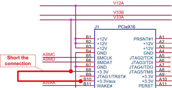
Figure 48 J1 Modification on AB18 for Alveo Connection
3) Short pin B8 and B10 of J1 connector.
For further information on the AB18 board, refer to the following document.
https://dgway.com/products/IP/ABseries/AB18-PCIEx16-MAN-E.pdf
Caution: The AB18 modification is a customized process undertaken by the user. As a result, Design Gateway does not guarantee the outcome of the modification.
5 Revision History
|
Revision |
Date (D-M-Y) |
Description |
|
4.09 |
9-Jan-26 |
- Support VHK158 - Support AB19-M2PCI and AB20-U2PCI |
|
4.08 |
12-Jul-23 |
Correct Figure 11 |
|
4.07 |
11-May-23 |
Support ZCU111 |
|
4.06 |
3-Feb-23 |
Update supported board lists for each PCIe IP model |
|
4.05 |
21-Jul-22 |
Support VCK190 |
|
4.04 |
16-Jun-22 |
Support raNVMe-IP and muNVMe-IP |
|
4.03 |
13-Sep-21 |
Support NVMe-IP for Gen4 |
|
4.02 |
22-Dec-20 |
Support NVMeG4-IP |
|
4.01 |
27-Aug-20 |
Support KCU116 |
|
4.00 |
29-Jun-20 |
Remove instruction from the document and include NVMeG3-IP |
|
1.00 |
2-Jun-16 |
Initial version release |