Boost Network Efficiency: How tCAM-based packet switching enhances data flow
In today’s world, the internet is a vast and bustling highway of information, with countless data packets constantly being sent to servers for processing. Unfortunately, not all of these packets have good intentions. Malicious activities, such as cyberattacks, can put a significant burden on servers, overwhelming them with unnecessary traffic and threatening their stability.
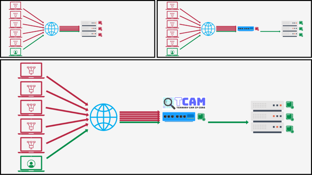
To address this issue, one common solution is to use routers or switches equipped with filtering functions. These devices can help reduce the load on servers by filtering out unwanted traffic before it reaches them. However, this shifts the burden to the routers or switches themselves. In the face of large-scale attacks, even these devices can struggle, potentially leading to network failures or other serious consequences.
In this presentation, we will introduce an innovative approach to alleviate the load on routers and switches. By leveraging TCAM (Ternary Content-Addressable Memory), we can enhance the efficiency of packet filtering, significantly reducing the strain on network infrastructure. This solution not only helps in maintaining server performance but also strengthens the overall resilience of the network.
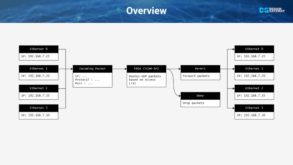
This overview introduces the UDP Packet Switching system, which processes Ethernet packets received from four channels.
The system utilizes TCAM-IP to analyze network parameters such as IP addresses and UDP ports.
The user defines specific rules to determine whether the packet should be denied or permitted, and to which channel the permitted packet will be forwarded.
tCAM Spectifications
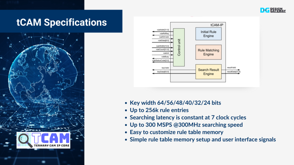
Now, let’s dive into the specifications of TCAM, the key component we’re utilizing to optimize our network’s performance.
Firstly, TCAM offers versatile key widths, allowing us to handle keys of 64, 56, 48, 40, 32, or even 24 bits. This flexibility ensures that we can adapt to various data formats and network protocols.
The TCAM can manage up to 256,000 rule entries, giving us extensive capacity to define and store filtering rules. This is crucial for maintaining a robust defense against unwanted traffic.
One of the standout features of TCAM is its constant searching latency of just 7 clock cycles, regardless of the number of entries. This consistency is vital for maintaining high-speed data processing without introducing delays.
In terms of speed, TCAM supports up to 300 million searches per second, operating at a frequency of 300 MHz. This high performance is essential for keeping up with modern, high-speed networks.
Additionally, TCAM is designed with ease of customization in mind. The rule table memory can be easily configured, allowing us to tailor the system to specific needs. The setup process is straightforward, with a simple user interface that makes it accessible even to those who may not be familiar with the underlying technology.
Hardware Setup
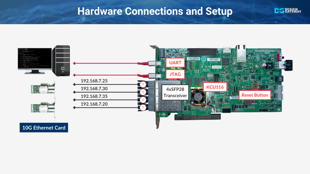
Let’s move on to the hardware setup for our demo. Here’s how the connections are made to ensure everything runs smoothly.
First, we’ll connect the 10Gb SFP+ cables from our KCU116 board to the PC. We have four SFP ports to manage, each connected to a different Network Interface Card, or NIC, on the PC.
- SFP0 is connected to the NIC with the IP address 192.168.7.25.
- SFP1 is connected to the NIC with the IP address 192.168.7.20.
- SFP2 is connected to the NIC with the IP address 192.168.7.35.
- SFP3 is connected to the NIC with the IP address 192.168.7.30.
These connections are critical for enabling high-speed data transfer and accurate packet switching during the demo.
Additionally, we need to establish a USB connection between the PC and the KCU116 board. This is done by connecting a USB cable from the PC to the JTAG and UART micro USB port on the board. This connection allows us to program the FPGA and monitor the system during the demo.
Command Overview
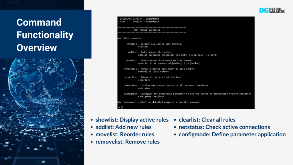
Now that our hardware is set up, let’s review the key functionalities available in this demo. These commands are essential for managing and controlling the UDP packet switching process:
- Showlist: This command displays the current list of rules or configurations in use. It’s perfect for quickly checking what rules are active.
- Addlist: With addlist, you can add new rules or configurations to the list. This is useful for updating the filtering criteria or modifying network behavior as needed.
- Movelist: This function allows you to reorder the rules in the list, moving them up or down to prioritize certain actions. It’s key to ensuring that the most important rules are processed first.
- Removelist: When a rule is no longer needed, removelist lets you remove it from the list, keeping the system streamlined and efficient.
- Clearlist: This command clears all entries in the list, resetting the system to a default state. It’s a quick way to remove all rules and start fresh.
- NetStatus: The netStatus command displays the current status of all network interfaces.
- Configmode: The configmode command allows you to specify whether the parameters in the list should be applied based on the source or destination of the network parameters. This flexibility is crucial for tailoring the system’s behavior to different scenarios.
Each of these functions is integral to thoroughly testing and managing the UDP packet switching demo, ensuring that everything operates as intended.
Repeater Mode Configuration

In this section, we will configure the system to operate in repeater mode, where all incoming data is forwarded to every port.
First, we set the configuration mode to ‘destination’ using the configmode des command.
Next, we add a list with the addlist 1111 IP ANY command, ensuring that any IP address will be forwarded to all ports.
We then verify the configuration using the showlist command.
Repeater Mode Demo
In this part, we demonstrate the results of the repeater mode configuration.
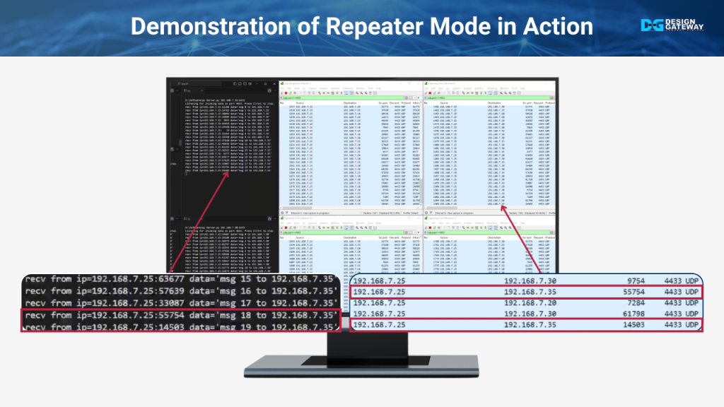
We start by running a UDP client on IP 192.168.7.25, which sends 20 packets to each of the specified IP addresses—192.168.7.20, 192.168.7.35, and 192.168.7.30. Meanwhile, four UDP servers on different IP addresses, all listening on port 4433, are ready to receive the data.
As the client sends the packets, you’ll see each server display the data received when the IP matches its own. However, when observing the Wireshark windows, you’ll notice that each interface receives all the data sent by the client, regardless of whether the IP matches the interface.
This demonstrates that while the servers correctly handle the data sent specifically to them, the repeater mode causes all data to be sent to every port. This unnecessary data flow can increase the load on servers, even though they only process relevant information.
Switching Mode Configuration
In this section, we’ll demonstrate the process of configuring the system to operate as a switch instead of a repeater. To begin, we’ll remove the existing configuration by using the removelist command. This step is crucial as it disables the repeater mode, which was previously set up to forward all received data to every port.
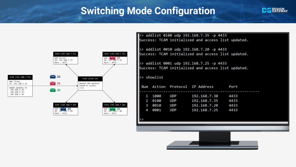
After clearing the repeater setup, we proceed to add new lists with the addlist command. Each rule will be carefully configured to allow only UDP traffic on port 4433, with specific IP addresses being directed to their respective SFP ports.
- The first rule directs data from IP 192.168.7.30 to SFP port 3.
- The second rule directs data from IP 192.168.7.35 to SFP port 2.
- The third rule directs data from IP 192.168.7.20 to SFP port 1.
- The fourth rule directs data from IP 192.168.7.25 to SFP port 0.
After setting up these rules, we will use the showlist command to verify that each IP address is correctly mapped to its designated SFP port. This ensures that the system is now functioning as a switch, with traffic being routed precisely as intended.
Switching Mode Demo
In this part, we will observe the results after configuring the system to function as a switch, which is expected to be different from the previous demonstration in repeater mode.
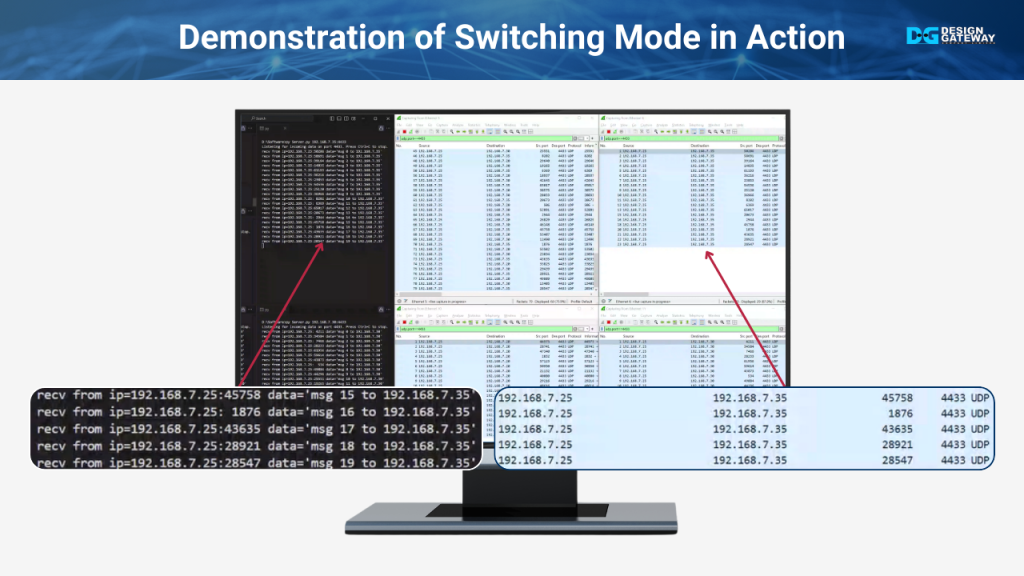
We’ll start by running the UDP client at IP 192.168.7.25, sending data to the UDP servers located at IPs 192.168.7.20, 192.168.7.30, and 192.168.7.35. On the server side, each UDP server will display the received data that corresponds with its own IP address.
This time, when monitoring the traffic using Wireshark, the key difference will be evident. Unlike the repeater mode, where all interfaces received all data packets, here, the data on each interface will match only the IP address of that specific interface.
This demonstrates that switching mode reduces the burden on the servers because they only process the relevant data. As a result, the servers are not overwhelmed by unnecessary packets, which enhances overall system efficiency and performance.
Packet Filtering Configuration

In this section, we will demonstrate how the system can be configured to filter out specific UDP packets.
The process begins with using the removelist 1 command to delete the rule that allows UDP packets destined for IP 192.168.7.30 on port 4433. This action filters out these packets
Finally, the results of this configuration are displayed using the showlist command.
Filtering Results
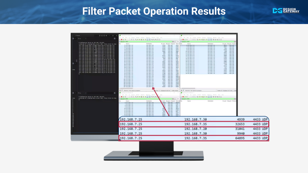
In this part, we’ll observe the results of filtering UDP packets. The UDP client sends data from IP 192.168.7.25 to IP 192.168.7.20, 192.168.7.30, and 192.168.7.35. The servers at 192.168.7.20 and 192.168.7.35 receive the data as expected, but the server at 192.168.7.30 shows no activity at all, as the packets destined for it have been filtered out.
When analyzing the Wireshark data, we see that while 192.168.7.25 sends packets to all three destinations, the interface at 192.168.7.30 receives nothing.
This confirms that our filter successfully blocks unwanted traffic, effectively preventing unnecessary data from reaching the server and reducing the potential for malicious attacks.
Ready to elevate your network performance with cutting-edge technology?
Contact us today to learn how our solutions can optimize your operations. Don’t forget to subscribe and stay tuned for more innovations!