Seamless Custom RTL Implementation on KR260 to Accelerate Applications
Implement custom RTL on KR260
The Kria KR260, based on the K26 System on Module (SOM), provides a unique environment for developing custom RTL designs. It integrates a Zynq UltraScale+ MPSoC, combining a high-performance ARM processor with FPGA fabric, allowing you to run a full operating system like Ubuntu on the processor while leveraging the FPGA for accelerated tasks.
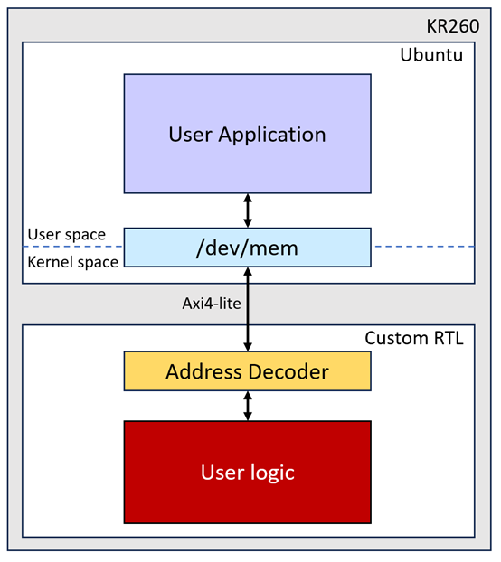
This document shows how the custom RTL and software are built for an application on KR260, as shown in Figure 1. Our AES256GCM10G25GIP is used as the example user logic to accelerate encryption-decryption process. For more information about our IP, please visit our website.
To build a custom RTL design on the KR260, we use Vivado2022.1. Let’s get started:
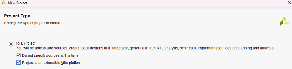
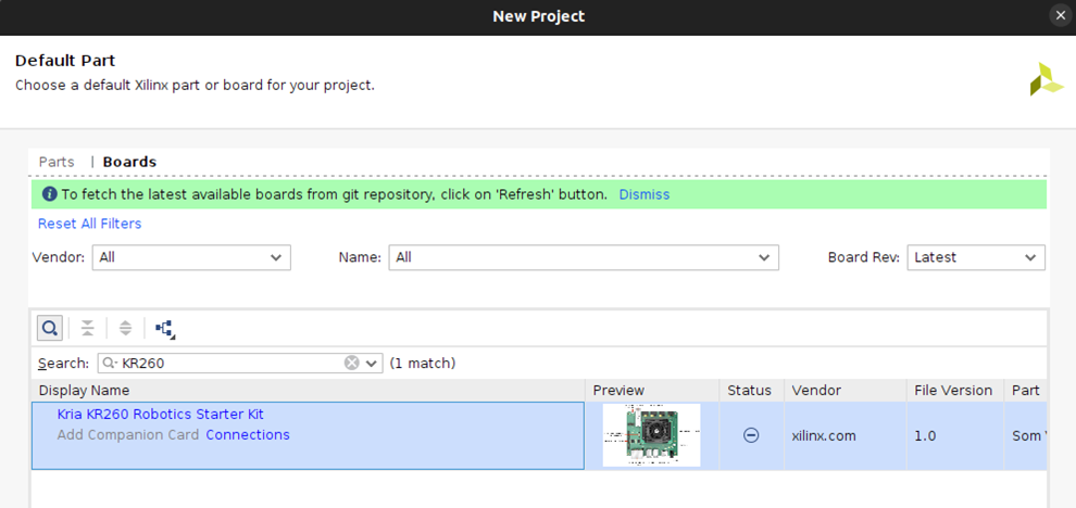
- Create a New Vivado Project:
- Start by creating a new project in Vivado and select the KR260 as the target board.
- Create Block Design:
- Create a new block design.
- Add the Zynq MPSoC Ultrascale+ component to the design.
- Run the auto block design on the Zynq MPSoC component.
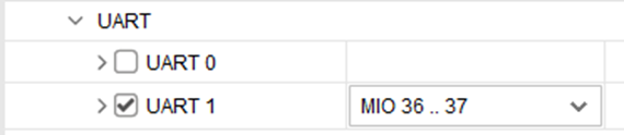
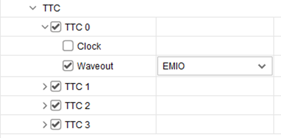
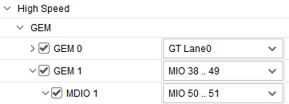
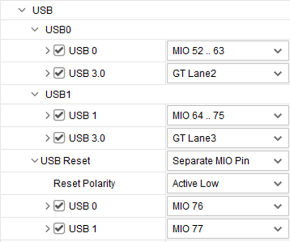
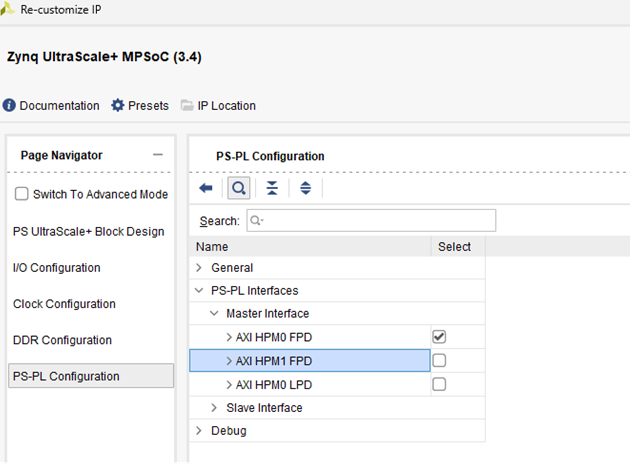
- Configure the Zynq MPSoC IP, go to I/O Configuration and enable the following peripherals:
- UART
- TTC
- GEM0 and GEM1
- USB 0 and USB 1
- Remove unused HPM port
- Add Necessary Components and Ports:
- Add the following components/Port:
- System Resets: Two system reset modules, as each clock output requires a reset.
- slice: Set to 3-bit datain and 1-bit dataout, used to drive the CPU fan.
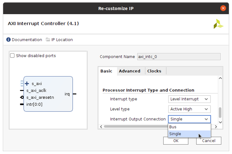
- AXI Interrupt Controller: Included to meet system requirements and change “Interrupt Output Connection” to “Single” so that it can be connected to PS IRQ interface.
- Ports: user_clk, axi_clk, axi_resetn, and S_AXI to map the interface of AES256GCM10G25GIP.
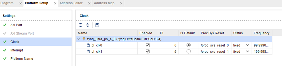
- Go to Platform Setup -> Clock -> Enable all used clocks and select one default clock.
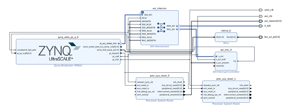
- Connect all component as shown, then validate design let vivado assign address mapping.
- Add the following components/Port:
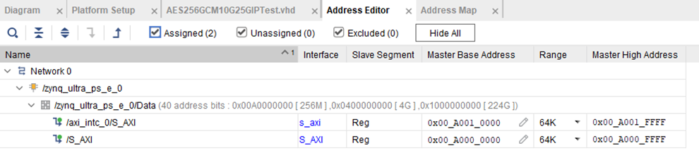
- Mapping External Ports:
- Ensure that the external ports from your block design are correctly mapped to your custom IP interface.
- Check our IP interface at https://dgway.com/products/IP/AES-IP/AES256GCM10G25GIP-refdesign-xilinx-en/
- Generate Bitstream:
- Configure the settings to enable the generation of a bin file.
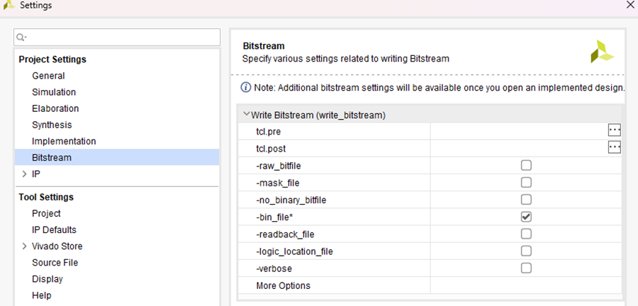
- Run synthesis, implementation and generate bitstream.
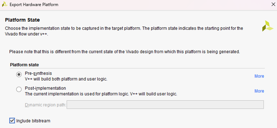
- Once the bitstream is generated, export the platform to obtain the XSA (Xilinx Support Archive) file.
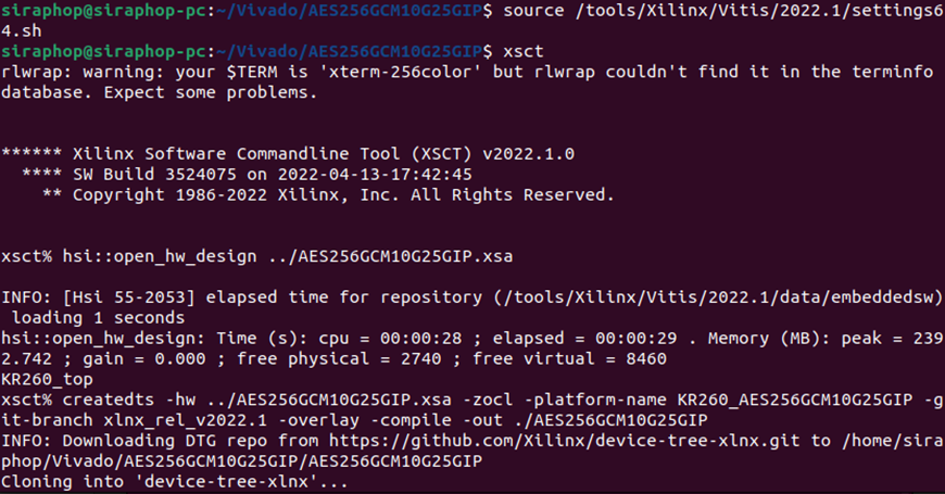
- Using XSCT (Xilinx Software Command-Line Tool) to Generate Device tree overlay:
- Open xsct and run following command:
- hsi::open_hw_design
- createdts -hw -zocl -platform-name -git-branch xlnx_rel_v2022.1 -overlay -compile -out
- Open xsct and run following command:
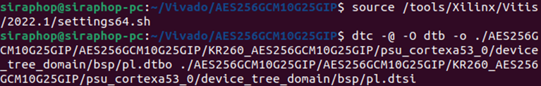
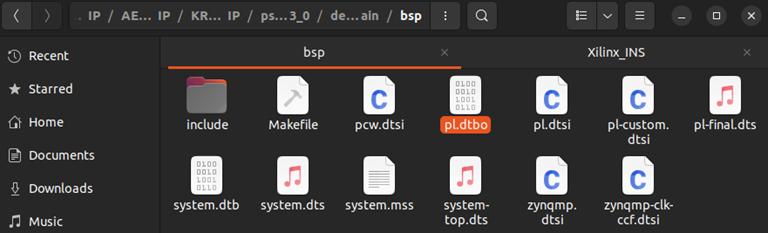
- Compile DTS Files into Device Tree Blob (dtbo):
- Use linux device tree compiler (dtc) to compile the source files into device tree blob with the following command:
- dtc -@ -O dtb -o
- Use linux device tree compiler (dtc) to compile the source files into device tree blob with the following command:
Note: The default name of dtbo is pl.dtbo. User can change the filename as desired.
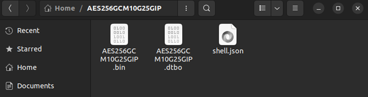
- Prepare application file for running on KR260:
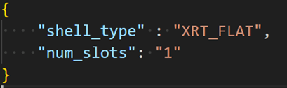
- Create description file(“shell.json”)
- Bitstream binary file
(<path to vivado project>/vivado.vivado.runs.impl_1/<xsa_name.bin>) - Device tree blob file
- Setup Ubuntu and application files on KR260
- Follow the instructions on the AMD setup guide to download and prepare the SD card image. (https://www.amd.com/en/products/system-on-modules/kria/k26/kr260-robotics-starter-kit/getting-started/setting-up-the-sd-card-image.html)
- After flashing SD card, connect it to host PC.
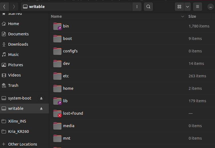
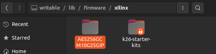
- Copy folder “AES256GCM10G25GIP” to “/lib/firmware/Xilinx” on SD card.
- Insert microSD card into the microSD card slot located under the KR260 board.
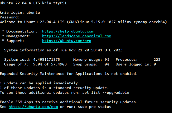
- Connect the power supply to the FPGA development board. The board will automatically boot into Ubuntu.
- Activate AES256GCM10G25GIP accelerator
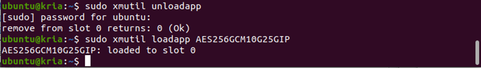
- Unload the default hardware application using command “sudo xmutil unloadapp”.
- Load new hardware application using command “sudo xmutil loadapp AES256GCM10G25GIP”.
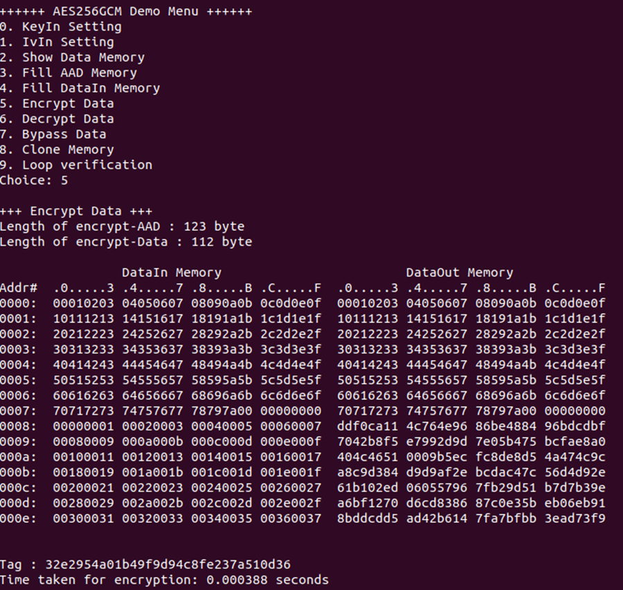
The AES256GCM10G25GIP accelerator is now active on our KR260. Before running a software application designed to interface with the accelerator, the software must be compiled. In this example, “aesgcmipdemo.c” is compiled using “gcc” on the KR260. Users can execute the “AES256GCM10G25GDEMO” application, which is accelerated by our IP, and observe the results as shown.

If you need any more information or further assistance, feel free to ask! https://dgway.com/index_E.html